Method for controlling synchronous impact of clutch
A control method and synchronous shock technology, applied in clutches, electric clutches, non-mechanical drive clutches, etc., to achieve the effect of strong real-time performance, simple control method and reduced shock
- Summary
- Abstract
- Description
- Claims
- Application Information
AI Technical Summary
Problems solved by technology
Method used
Image

Examples
Embodiment Construction
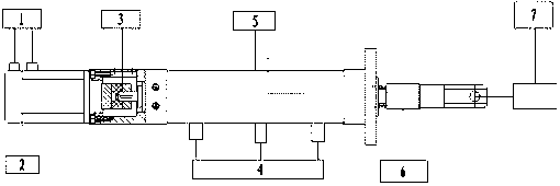
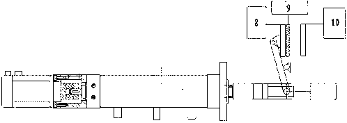
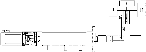
[0030] The present invention is further elaborated below in conjunction with accompanying drawing, the present invention has adopted electric automatic clutch. as attached figure 1As shown, the electric automatic clutch system is composed of servo motors, couplings, ball screws and other mechanisms, and is equipped with encoders, position sensors, and limit sensors. In the present invention, a 16-bit microcontroller of the FreeScale MC9S12DT128 type sends out pulse signals to control the motion of the servo motor, and the rotation of the servo motor drives the ball screw to convert the rotary motion into a forward and backward linear motion. Through the linear motion of the ball screw, the release lever of the clutch is pushed to realize the separation and combination of the clutch. When the single-chip microcomputer sends out a pulse, it also sends out a high level or a low level to control the rotation direction of the servo motor and realize the forward and backward of the...
PUM
 Abstract
Description
Claims
Application Information
PatSnap Eureka turns technology decisions into work you can execute. Powered by our Innovation Knowledge Graph, it runs expert workflows across engineering, life sciences, materials and intellectual property. Get your review-ready output in minutes.


