
Indoor unit of air conditioner

A technology for indoor units and fans of air conditioners, applied in air conditioning systems, space heating and ventilation, household heating, etc., can solve problems such as the influence of air supply range and difficulty in meeting high static pressure requirements, and increase the air supply distance , good air supply effect, simple and reasonable structure

Inactive Publication Date: 2012-10-03
GD MIDEA AIR-CONDITIONING EQUIP CO LTD
View PDF6 Cites 27 Cited by
  • Summary
  • Abstract
  • Description
  • Claims
  • Application Information

AI Technical Summary

Problems solved by technology

That is to say, there are air outlets in the four directions on the upper part of the vertical air conditioner, that is, a diffuser, and the fan adopts an axial fan. Device, volute, air outlet and air guide vanes, etc., plus a long air duct, after the treated air is discharged from the air outlet, it is required to send a relatively long distance, so in order to meet the comfort requirements of users, it is necessary The fan provides high static pressure. It is difficult to meet the high static pressure requirement only by the axial flow fan in the scheme. In addition, the air supply direction of the axial flow fan is upward, and it is discharged in four directions after reaching the top. Since there is no tangential direction The sub-wind speed, the range of air supply will be affected

Method used


Image

  • Indoor unit of air conditioner
  • Indoor unit of air conditioner
  • Indoor unit of air conditioner

Examples


no. 1 example

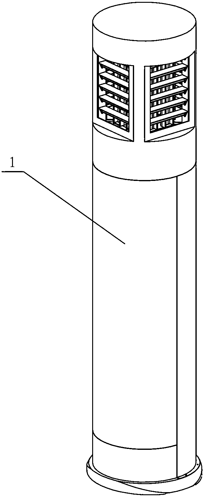
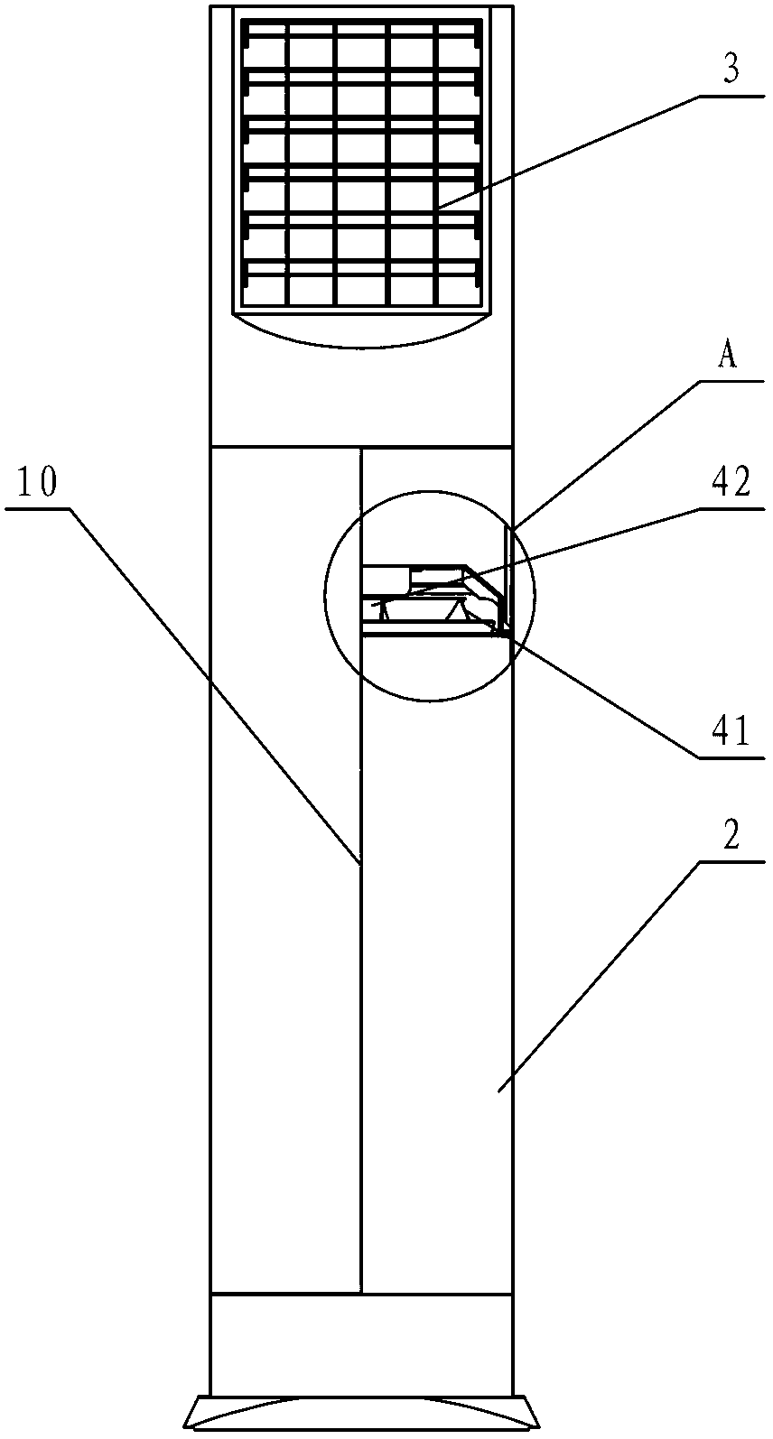
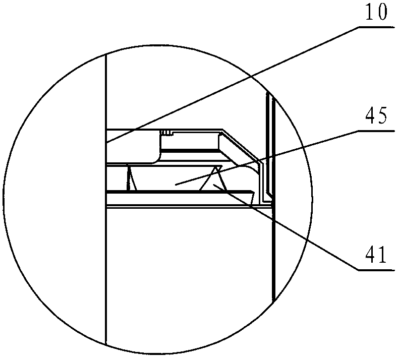
[0042] see Figure 1-Figure 6 , the indoor unit of the air conditioner includes a fan and a heat exchanger (not shown in the figure) arranged in the casing 2, and the casing 2 is provided with an air inlet (not shown in the figure) and an air outlet 3, and the casing 2 is provided with an air duct, and the fan is arranged in the air duct, and the fan is a diagonal flow fan 4 .

[0043] In this embodiment, an air passage for communicating air from the air inlet to the air outlet 3 is provided in the casing 2 , and a diagonal flow fan 4 is arranged in the air passage. The oblique flow fan 4 is also called a mixed flow fan, and the air supply direction of the oblique flow fan 4 includes a component along the axial direction of the motor and a component along the tangential direction of the impeller rotation direction. The air supply volume of the oblique flow fan 4 is smaller than that of the axial flow fan, but greater than that of the centrifugal fan. The air supply static pr...

no. 2 example

[0046] see Figure 7-Figure 12 The difference between this embodiment and the first embodiment is that a volute 5 is arranged on the inner wall surface of the housing 2 of the indoor unit of the air conditioner, such as Figure 7 and Figure 8As shown, the inner wall surface corresponding to the hub 45 of the diagonal flow fan 4 and the fan blade 41 is provided with a volute 5 , and the volute 5 is fixed on the inner wall surface of the casing 2 through the volute connecting portion 17 . The volute 5 itself has a certain strength, and the inner surface of the volute 5 has high processing accuracy and surface smoothness, which is beneficial to cooperate with the rotating fan blade 41, which can facilitate the passage of air and reduce air resistance.

[0047] pass Figure 8 It can be seen from the local enlargement that there is a gap 7 between the volute 5 and the inner wall of the casing 2. When the air cooled or heated by the heat exchanger flows through the volute 5, the ...

no. 3 example

[0052] see Figure 13-Figure 15 The difference between this embodiment and the first embodiment is that the air outlet 16 of the oblique flow fan 4 is provided with a diffuser cone 11 coaxial with the hub 45, that is, the larger diameter side of the hub 45 is provided with a cone 11 coaxial with the hub 45. Coaxial diffuser cone 11, the diffuser cone 11 is a frustum-shaped structure with a large diameter on the air inlet side and a small diameter on the air discharge side. The diffuser cone 11 is fixed on the motor support 6, and an air duct is formed between the outer surface of the diffuser cone 11 and the inner surface of the housing 2 of the indoor unit (also the inner surface of the volute 5), and the air duct is a A circular structure with a small lower area and a larger upper area. The gradually enlarged air duct formed in this way can effectively diffuse the air, reduce the air speed and flow loss, and increase the static pressure of the air and the air supply distanc...


PUM


Abstract

The invention relates to an indoor unit of an air conditioner. The indoor unit comprises a fan and a heat exchanger which are arranged in a shell body; the shell body is provided with an air inlet and an air outlet; an air channel is arranged in the shell body; the fan is arranged in the air channel; and the fan is an oblique-flow fan. The oblique-flow fan comprises a wheel hub, a plurality of fan blades, a motor and a driving shaft, wherein the motor is used for driving the oblique-flow fan to rotate, and the driving shaft is used for connecting the motor with the wheel hub; the diameter of the air inlet side of the wheel hub is relatively small; the diameter of the air outlet side of the wheel hub is relatively big; and the fan blades are arranged at the windward side of the wheel hub. A volute is arranged on an internal wall face corresponding to the wheel hub and the fan blades of the oblique-flow fan and is fixedly arranged on the internal wall of the shell body. A gap is arranged between the volute and the internal wall of the shell body. An insulating layer or noise-absorbing layer is filled in the gap. A wind wheel cover encircling the fan blades is arranged among the top faces of the fan blades, and the lower part of the wind wheel cover is small and the upper part of the wind wheel cover is big. An inlet air guide ring is arranged at the air inlet of the oblique-flow fan. The indoor unit of the air conditioner has the characteristics of simple and reasonable structure, flexibility in operation, and good air supply effect.

Description

technical field [0001] The invention relates to an air conditioner, in particular to an indoor unit of the air conditioner. Background technique [0002] At present, the indoor unit of the air conditioner is used as a processing device for indoor air, and it is also used as an indoor decoration. Users not only have requirements for its performance, but also have various requirements for its fashionable and beautiful appearance. [0003] Chinese Patent Document No. CN 1782515A disclosed an indoor unit of an air conditioner on June 7, 2006. The cross-section mentioned in its background technology is a rectangular floor-standing air conditioner. The centrifugal fan in the lower part passes the pressurized air upwards through the heat exchanger, and then blows to the indoor space through the air outlet. As the society has higher and higher requirements for energy saving, the energy efficiency standards of air conditioners that can be launched on the market are continuously impr...

Claims


Application Information

Patent Timeline
Patent Type & Authority Applications(China)
IPC IPC(8): F24F1/00F24F13/02F24F13/24
Inventor 蔡序杰黎文斗张智周拨刘阳
Owner GD MIDEA AIR-CONDITIONING EQUIP CO LTD
Learn More