Rotating motor, electric pressure fan and device

A technology of rotating motors and rotating shafts, applied in mechanical equipment, machines/engines, non-variable pumps, etc., can solve problems such as uncontrollable costs, inconsistent characteristics, and no improvement in losses, so as to reduce material costs and reduce material costs Effect

Active Publication Date: 2011-09-28
PANASONIC INTELLECTUAL PROPERTY MANAGEMENT CO LTD
View PDF9 Cites 0 Cited by
  • Summary
  • Abstract
  • Description
  • Claims
  • Application Information

AI Technical Summary

Problems solved by technology

As shown in the above example, the method of specifying the core punching direction in consideration of the magnetic characteristics and the method of changing the frame width have no effect on the loss of material at both ends of the ferrule width direction.
In addition, when using the die without discarding both ends in the width direction of the hoop, when the ends in the width direction of the hoop are used, the inconsistency of characteristics becomes large, and appropriate cost control cannot be performed.

Method used


Image

  • Rotating motor, electric pressure fan and device
  • Rotating motor, electric pressure fan and device
  • Rotating motor, electric pressure fan and device

Examples


Embodiment Construction

[0023] Hereinafter, an electric blower using a rotating electrical machine according to an embodiment of the present invention will be described with reference to the drawings.

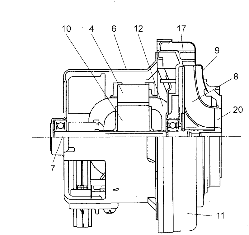
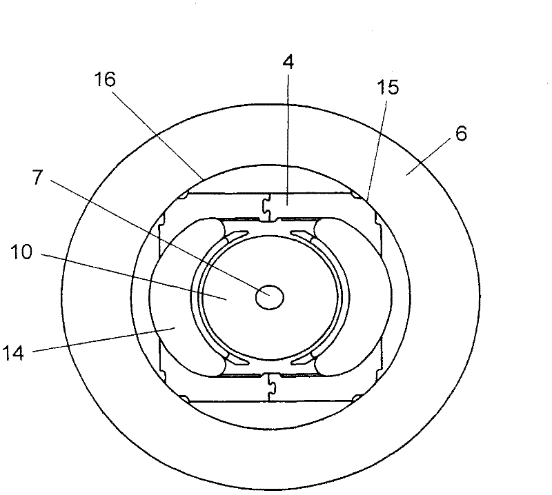
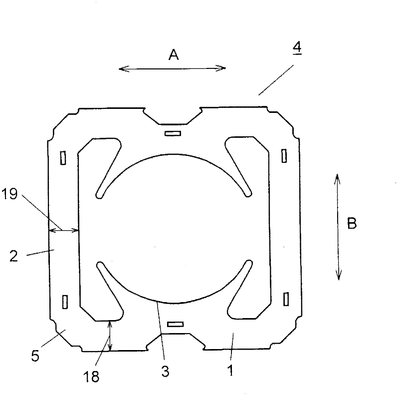
[0024] figure 1 It is a partial sectional view showing the structure of the electric blower according to the embodiment of the present invention, figure 2 It is a partial cross-sectional view showing a state in which a field magnet is pressed into a bracket of an electric blower according to an embodiment of the present invention, image 3 It is an explanatory diagram showing a field core in which a salient pole portion is provided on a frame formed in the steel sheet rolling direction.

[0025] exist Figure 1 ~ Figure 3 Among them, the electric blower 11 is provided with a rotating motor in a cylindrical bracket 6 that closes the opening in the opposite direction on one side. The rotating electric machine is roughly constituted by a field magnet 12 and an armature 10 . The field magnet 12 has ...


PUM


Abstract

The invention provides a rotating motor. An excitation iron core is provided with a squre-shaped frame formed by a pair of edge frames in a steel plate rolling direction and a pair of edge frames in a direction orthogonal to the steel plate rolling direction. The edge frames formed in the steel plate rolling direction is wider than those in the direction orthogonal to the steel plate rolling direction (or hoop width direction) in width, and is provided with a protruding portion used for edge frames in the steel plate rolling direction to wind a field magnetic winding. In this case, the lost of materials in the hoop width direction can be improved.

Description

technical field [0001] The present invention relates to a rotating electrical machine such as a generator or a motor, an electric blower mounted on an electric vacuum cleaner or the like to rotate a fan by power of the motor to blow air, and an apparatus equipped with the electric blower. Background technique [0002] Generally, a commutator motor is used as a motor unit of an electric blower mounted on an electric vacuum cleaner. The field magnet of this motor is formed by winding a coil in a square cylindrical iron core. Inside the barrel there is an armature freely rotatable. The iron core is formed by laminating multiple layers of steel plates, which are manufactured by punching rolled non-directional electrical steel plates. [0003] Figure 5 It is a partial sectional view showing the structure of a conventional electric blower, Figure 6 It is a partial cross-sectional view showing a state in which a field magnet is pressed into a bracket of a conventional electric...

Claims


Application Information

Patent Timeline
Patent Type & Authority Applications(China)
IPC IPC(8): H02K1/06F04D25/08
Inventor 嶋崎哲夫藤田克敏冈田幸弘
Owner PANASONIC INTELLECTUAL PROPERTY MANAGEMENT CO LTD
Why Eureka
Try Eureka