Flexural fatigue testing machine
A bending fatigue and testing machine technology, applied in the direction of applying repeated force/pulsation force to test the strength of materials, etc., can solve the problems of complex equipment structure, low work efficiency, long test period, etc., and achieve high work efficiency, simple structure, and test short cycle effect
- Summary
- Abstract
- Description
- Claims
- Application Information
AI Technical Summary
Problems solved by technology
Method used
Image
Examples
Embodiment 1
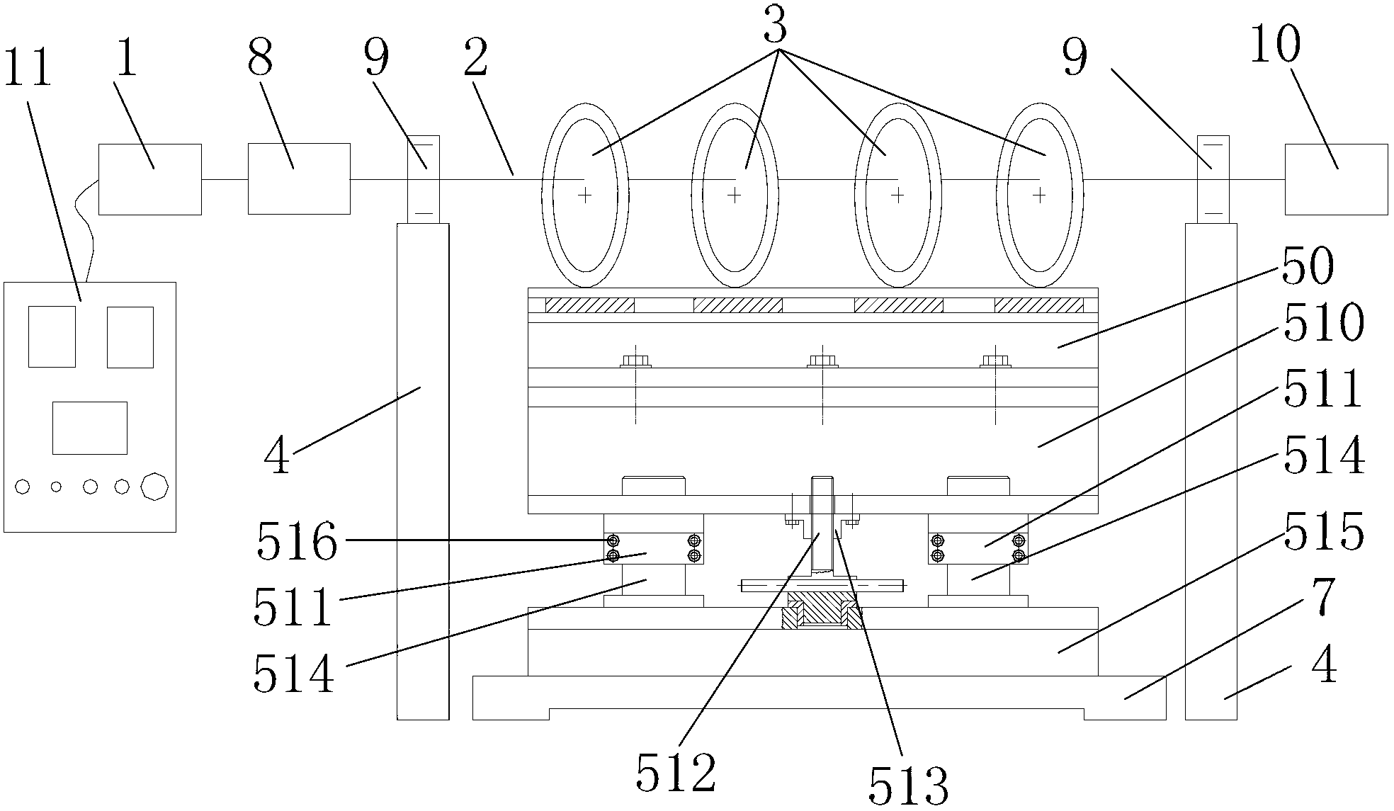
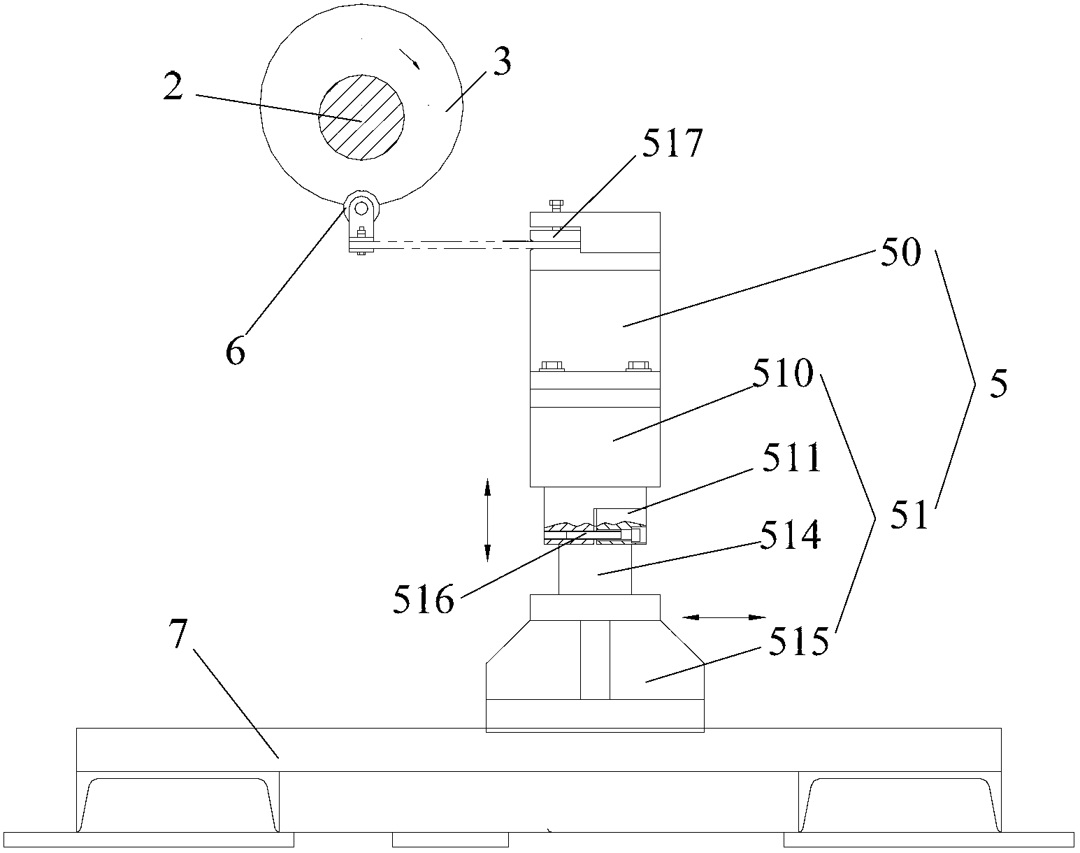
[0055] Such as figure 1 with figure 2As shown, a bending fatigue testing machine provided by an embodiment of the present invention includes: the hydraulic motor 1 is connected with the reducer 8, the hydraulic motor 1 is connected with the control device 11, the reducer 8 is connected with one end of the main shaft 2, and the main shaft The other end of 2 is connected with the counter 10, the main shaft 2 is rotatably connected with the main shaft support seat 4 through the bearing 9, the sample rack 5 is installed on the base 7 provided with guide rails, the sample rack 5 includes a sample holder 50 and a test The sample support frame body 51, the sample support frame body 51 includes a clamp mounting base 510, a locking block 511, a screw 512, a nut 513, two symmetrically arranged guide posts 514 and a connecting seat 515, and the sample clamp 50 is detachably fixed Installed on the fixture mount 510, the upper end of the guide post 514 that is symmetrically arranged is s...
Embodiment 2
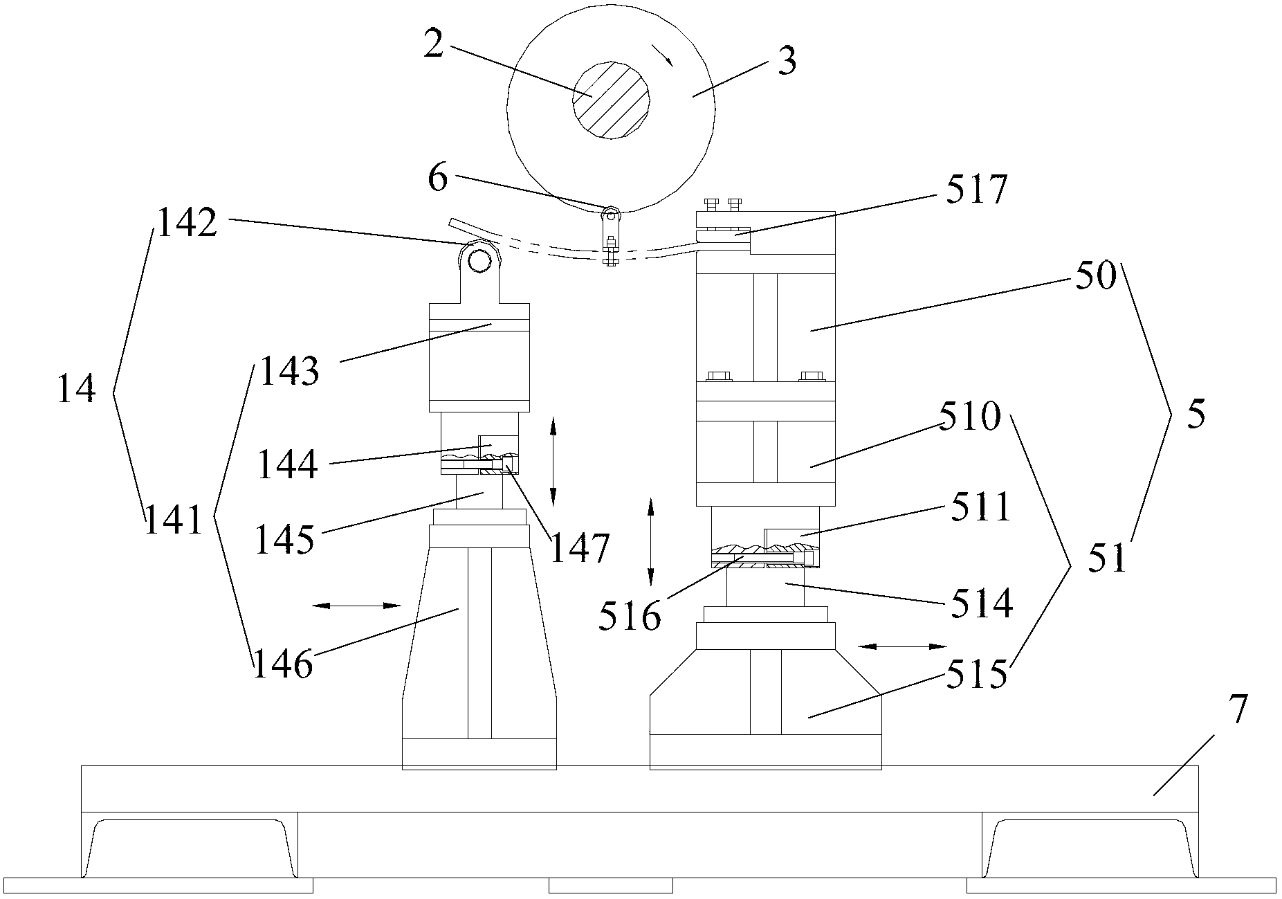
[0060] Such as figure 1 with 3 As shown, another embodiment of the bending fatigue testing machine of the present invention is shown. Compared with the fatigue testing machine described in the above-mentioned embodiment 1, this fatigue testing machine also includes a sample support frame 14, and the sample support frame 14 Comprise support frame body 141 and support roller 142, support roller 142 is installed on the upper end of support frame body 141, support roller 142 supports sample, support frame body 141 includes support head 143, support locking block 144, support screw, support nut, Symmetrically arranged support guide posts 145 and support base 146, the sample support frame 14 is installed on the base 7 provided with guide rails through the support base 146, the support base 146 can move along the guide rails, and after the support frame 14 moves to the required position, The supporting base 146 can be fixed on the base 7 by bolts; the upper end of the symmetrically ...
PUM
 Abstract
Description
Claims
Application Information
 - R&D
- Intellectual Property
- Life Sciences
- Materials
- Tech Scout
- Unparalleled Data Quality
- Higher Quality Content
- 60% Fewer Hallucinations
Browse by: Latest US Patents, China's latest patents, Technical Efficacy Thesaurus, Application Domain, Technology Topic, Popular Technical Reports.
© 2025 PatSnap. All rights reserved.Legal|Privacy policy|Modern Slavery Act Transparency Statement|Sitemap|About US| Contact US: help@patsnap.com


