Gas desorption instrument

A desorption and gas technology, applied in the direction of instruments, analytical materials, etc., can solve the problems of water shortage, large water consumption, and fragile measuring tubes.

Inactive Publication Date: 2012-10-03
CCTEG SHENYANG RES INST
View PDF4 Cites 12 Cited by
  • Summary
  • Abstract
  • Description
  • Claims
  • Application Information

AI Technical Summary

Problems solved by technology

Its disadvantages are that it is bulky, requires a horizontal surface to place the water tank 24, consumes a lot of water, sometimes lacks water in the field or underground, and the measuring tube 21 is fragile, etc.

Method used


Image

  • Gas desorption instrument
  • Gas desorption instrument
  • Gas desorption instrument

Examples


Embodiment 1

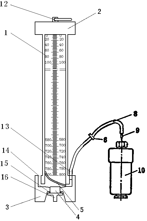
[0015] like figure 2 As shown, the gas desorption instrument of this embodiment includes a measuring tube 1, an exhaust rubber hose 8 and a puncture needle 9. The top end of the measuring tube 1 is provided with an upper cover 2, and a lifting ring 12 is installed on the upper cover 2. The measuring tube The bottom end of 1 is provided with a base 3, the middle part of the base 3 is provided with a water inlet 4, the water inlet 4 is provided with a plug 16, and a sealing ring 15 is arranged between the plug 16 and the water inlet 4, between the base 3 and the measuring tube 1 A drain 14 is formed between them, and the drain 14 communicates with the lower part of the measuring tube 1 in the form of a "U"-shaped pipe. A hose 5 is arranged inside the measuring tube 1 , and an air inlet 13 is opened on the base 3 , and the air inlet 13 communicates with the measuring tube 1 through the connecting hose 5 . There is a scale on the measuring tube 1. The hose 5 is connected to the...

Embodiment 2

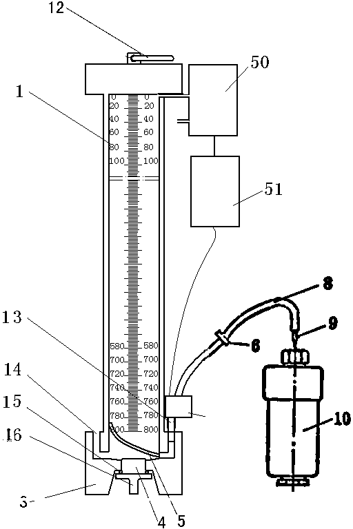
[0019] like image 3 As shown, the gas desorption instrument of this embodiment includes a measuring tube 1, an exhaust rubber hose 8 and a puncture needle 9. The top end of the measuring tube 1 is provided with an upper cover 2, and a lifting ring 12 is installed on the upper cover 2. The measuring tube The bottom end of 1 is provided with a base 3, the middle part of the base 3 is provided with a water inlet 4, the water inlet 4 is provided with a plug 16, and a sealing ring 15 is arranged between the plug 16 and the water inlet 4, between the base 3 and the measuring tube 1 A drain port 14 is formed in between, a hose 5 is arranged in the measuring tube 1, an air inlet 13 is opened on the base 3, a solenoid valve 52 is installed on the air inlet 13, and the air inlet 13 connects with the exhaust rubber hose through the solenoid valve 52 8 are connected, the exhaust rubber hose 8 is connected with the coal sample tank 10 through the puncture needle 9, and the spring clip 6 i...


PUM


Abstract

The invention relates to a gas desorption instrument. The gas desorption instrument comprises a measuring tube, an exhaust rubber tube and a puncture needle; an upper cover is arranged on the top of the measuring tube; a hoisting ring is arranged on the upper cover; a base is arranged at the bottom of the measuring tube; the base is provided with a water inlet; a plug is arranged on the water inlet; a water outlet is formed between the base and the measuring tube; a hose is arranged in the measuring tube; the base is provided with an air inlet; the hose is connected with the exhaust rubber tube through the air inlet; the exhaust rubber tube is connected with a coal sample tank through the puncture needle; and a spring clip is arranged on the exhaust rubber tube. The gas desorption instrument is simple and compact in structure, small in size, light in weight, easy to transport, convenient to carry and low in water consumption, facilitates wild or underground operation, and is suitable for water-free measuring sites; because the hoisting ring is arranged on the upper cover and the base is arranged at the lower end of the measuring tube, the instrument is easy to level; and when the instrument is used, the hoisting ring can be tied on a rope to hoist the instrument, or the instrument is placed on a horizontal plane.

Description

technical field [0001] The invention belongs to the technical field of coal seam gas content measurement, in particular to a gas desorption instrument. Background technique [0002] The direct methods for coal seam gas content determination include: geological exploration borehole gas desorption method, downhole borehole gas desorption method and coal core extractor method, etc. The basic method is to take coal cuttings or coal cores when the coal seam is just exposed, quickly put them into an airtight container, measure the desorption speed and desorption amount Q2, use the desorption law to deduce and compensate the total amount Q1 of the escaped part during the sample collection process, and then Go back to the laboratory to measure the remaining amount of gas Q3 in the coal sample, and finally get the gas content Q=Q1+Q2+Q3. In the process of measuring the gas residual quantity Q3 in the laboratory, first use the degassing device to measure the gas quantity Q31 b...

Claims


Application Information

Patent Timeline
IPC IPC(8): G01N7/14
Inventor 王魁军富向曹尧林王宇鹍王振伟杨鹏陈杰
Owner CCTEG SHENYANG RES INST
Why Eureka
Try Eureka