
Display device driving method and display device

A display device and gate driver technology, which is applied to static indicators, instruments, etc., can solve problems such as large coupling capacitance, and achieve the effect of improving stability and image quality

Inactive Publication Date: 2012-10-03
BOE TECH GRP CO LTD +1
View PDF5 Cites 9 Cited by
  • Summary
  • Abstract
  • Description
  • Claims
  • Application Information

AI Technical Summary

Problems solved by technology

However, there is usually a coupling capacitance between the data line and the common electrode, and the design of the high-load product results in a larger coupling area between the data line and the common electrode, that is, a larger coupling capacitance

Method used


Image

  • Display device driving method and display device
  • Display device driving method and display device
  • Display device driving method and display device

Examples


Embodiment Construction
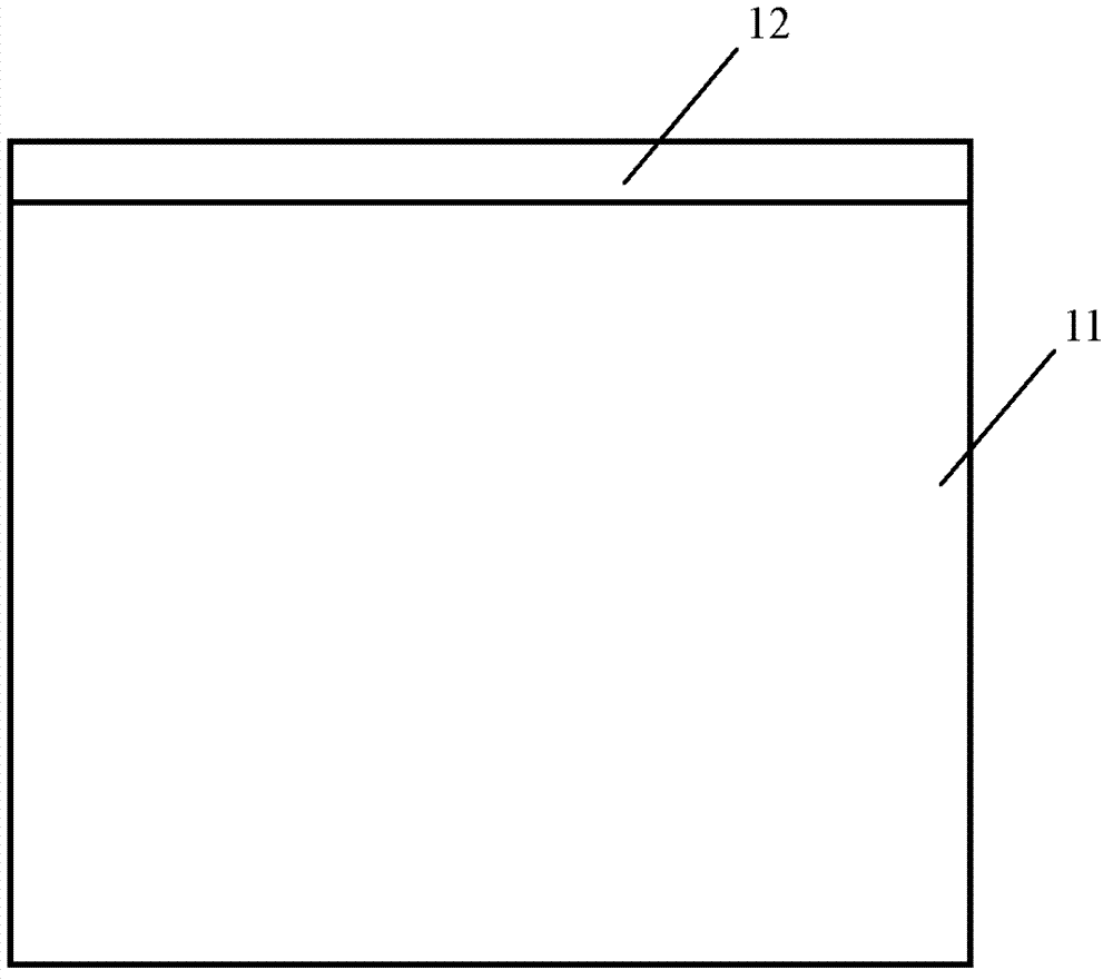
[0015] The display area of ​​the display device is defined by a plurality of intersecting data lines and gate lines. Because the gate lines are scanned and opened row by row, each row of gate lines can also be called a scan row. During the scanning process, the scanning always starts from the upper left corner of the image and moves forward horizontally, while the scanning point also moves downward at a slower rate. When the scanning point reaches the right edge of the image, the scanning point quickly returns to the left, and restarts to scan the second line below the starting point of the first line. The return process between lines is called horizontal blanking. A complete image scanning signal is composed of all line signal sequences separated by horizontal blanking intervals, called a frame. After the scanning point scans a frame, it needs to return from the lower right corner of the image to the upper left corner of the image to start scanning a new frame. This time inte...


PUM


Abstract

The invention discloses a display device driving method and a display device. The display device comprises a grid driver and a source electrode driver. Scanning lines are sequentially unpacked one by one from scanning signals output by the grid driver, and the scanning lines in set number correspond to a frame picture. When the scanning lines are unpacked, data signals output from the source electrode driver are input into pixel units of the scanning lines through a data line, and a coupling capacitor is arranged between the data line and a public electrode. The display device driving method includes inputting set data signals into the data line for offsetting coupling action of the data line to the public electrode during unpacking the scanning line corresponding to the frame picture at the field blanking time before unpacking the first scanning line corresponding to one frame picture. Accordingly, the public electrode can be driven in a manner of fluctuation complementing with the data signals of the frame picture during unfolding the frame picture, and voltage of the public electrode is stabilized and stability of the picture is improved.

Description

technical field [0001] The invention relates to the field of display technology, in particular to a driving method of a display device and a display device. Background technique [0002] Thin Film Transistor-Liquid Crystal Display (TFT-LCD) has the characteristics of small size, low power consumption, and no radiation, and occupies a dominant position in the current flat panel display market. With the rapid development of TFT-LCD, large-sized and low-cost high-load products, such as large-sized televisions (television, TV), appear. The emergence of this type of product puts forward higher requirements for picture quality. [0003] In the prior art, when a thin film transistor (Thin Film Transistor, TFT) pixel is working normally, the scanning lines corresponding to a frame of picture are sequentially turned on line by line, and when a scanning line is turned on, the data signal is input into the scanning line through the data line. pixel unit. However, there is usually a ...

Claims


Application Information

Patent Timeline
IPC IPC(8): G09G3/36
CPCG09G3/36G09G3/3611
Inventor 王洁琼
Owner BOE TECH GRP CO LTD
Features
  • Generate Ideas
  • Intellectual Property
  • Life Sciences
  • Materials
  • Tech Scout
  • Unparalleled Data Quality
  • Higher Quality Content
  • 60% Fewer Hallucinations
Learn More