
Laminating machine capable of driving film discharging by rotary loading

A technology of rotary feeding and stacking machine, which is applied in the field of battery cell manufacturing and battery manufacturing equipment, can solve the problems of low production efficiency of equipment, high manufacturing cost of stacking machine, large inertia of moving parts, etc., and achieve low manufacturing cost , maintenance and repair is simple, the effect of small motion inertia

Active Publication Date: 2012-10-03
DONGGUAN ARECONN PRECISION MACHINERY
View PDF4 Cites 21 Cited by
  • Summary
  • Abstract
  • Description
  • Claims
  • Application Information

AI Technical Summary

Problems solved by technology

[0004] The shortcoming of the laminate machine of prior art is: 1, mechanism is more, and structure is complicated, and floor area is big
2. The inertia of the moving parts is large, the running speed of the mechanism is slow, and the production efficiency of the equipment is low
3. The manufacturing cost of the stacking machine is high, the production cycle is long, and maintenance is difficult

Method used


Image

  • Laminating machine capable of driving film discharging by rotary loading
  • Laminating machine capable of driving film discharging by rotary loading

Examples


Embodiment Construction

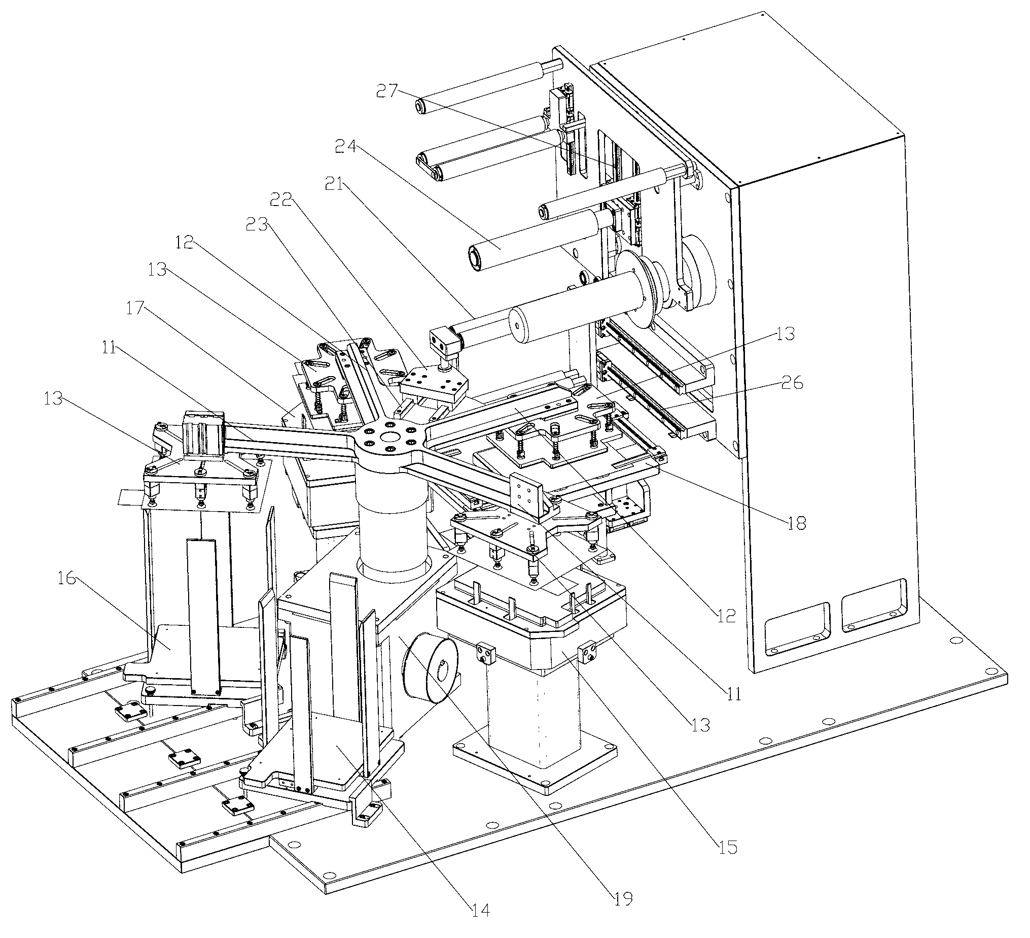
[0024] In order to further illustrate the principle and structure of the present invention, preferred embodiments of the present invention will now be described in detail with reference to the accompanying drawings.

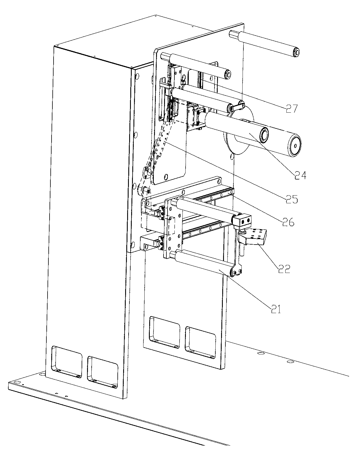
[0025] figure 1 It is a structural schematic diagram of an embodiment of a lamination machine in which rotating feeding drives film discharging according to the present invention, figure 2 It is a schematic diagram of the discharging mechanism of the stacking machine embodiment.

[0026] As shown in the figure, the lamination machine of the present invention, which drives film discharge by rotating feeding, includes a rotating feeding mechanism for transferring battery pole pieces. A cam splitter is used to drive the large turntable to rotate reciprocally. There are four feeding arms on the big turntable, among which the front feeding arm 11 with the two largest included angles is the rear feeding arm 12 with the smallest included angle. The big turntable is p...


PUM


Abstract

The invention relates to a laminating machine capable of driving film discharging by rotary loading. The laminating machine comprises a rotary loading mechanism, a positive pole piece trough, a positive pole piece calibration console, a negative pole piece trough, a negative pole piece calibration console, a lamination table and a film discharging mechanism, wherein the rotary loading mechanism is used for transferring pole pieces, and a big turntable which rotates in a reciprocating manner and is provided with four feeding arms is arranged at the upper part of the rotary loading mechanism; the positive pole piece trough, the positive pole piece calibration console, the negative pole piece trough, the negative pole piece calibration console and the lamination table are distributed along the periphery of the rotary loading mechanism; and the film discharging mechanism is arranged above the lamination table and driven by the big turntable which rotates in a reciprocating manner. When the big turntable rotates in a reciprocating manner, the two front feeding arms are used for respectively transferring positive pole pieces in the positive pole piece trough and negative pole pieces in the negative pole piece trough into the positive pole piece calibration console and the negative pole piece calibration console to be positioned; and the two rear feeding arms are used for respectively transferring the positioned positive pole pieces in the positive pole piece calibration console and the positioned negative pole pieces in the negative pole piece calibration console onto the lamination table and enabling the positive pole pieces and the negative pole pieces to be sequentially and alternately laminated with repeated Z-shaped films intermittently discharged by the film discharging mechanism. The laminating machine disclosed by the invention is simple in mechanisms for loading, transferring and laminating the positive pole pieces and the negative pole pieces in the circumferential direction, small in motion inertia, more stable in operation, small in occupied area and low in manufacturing cost.

Description

technical field [0001] The present invention relates to the technical field of battery manufacturing equipment, in particular to the technical field of battery cell manufacturing, and in particular to a method for stacking pole pieces and separators of cells, and sequentially stacking them, and a stacking device thereof. Background technique [0002] The stacking machine in the prior art includes: a positive electrode sheet feeding mechanism of the electrode sheet feeding part, a positive electrode sheet front feeding mechanism, a positive electrode sheet positioning mechanism, a positive electrode sheet rear feeding mechanism, a negative electrode sheet discharging mechanism, a negative electrode sheet front feeding mechanism, Negative electrode sheet positioning mechanism, negative electrode sheet rear feeding mechanism; and stacking mechanism, separator feeding mechanism, separator correcting positioning mechanism, forward material moving mechanism, separator cutting mecha...

Claims


Application Information

Patent Timeline
IPC IPC(8): H01M10/04
CPCY02E60/12Y02E60/10Y02P70/50
Inventor 陈保成
Owner DONGGUAN ARECONN PRECISION MACHINERY
Learn More