Terminal pin plugging device

A pin insertion device and terminal technology, which is applied in the assembly/disassembly of contact parts, contact part manufacturing, etc., can solve the problems that cannot meet the requirements of miniaturization and high-density terminal processing, etc.

Active Publication Date: 2012-10-03
SUZHOU HARMONTRONICS AUTOMATION TECH CO LTD
View PDF5 Cites 36 Cited by
  • Summary
  • Abstract
  • Description
  • Claims
  • Application Information

AI Technical Summary

Problems solved by technology

Obviously, this traditional method of manually inserting terminals into the workpiece cannot meet the current processing requirements for miniaturized and high-density terminals.

Method used


Image

  • Terminal pin plugging device
  • Terminal pin plugging device
  • Terminal pin plugging device

Examples


Embodiment Construction

[0025] In order to better understand the technical solution of the present invention, a preferred embodiment provided by the present invention will be described in detail below in conjunction with the accompanying drawings.

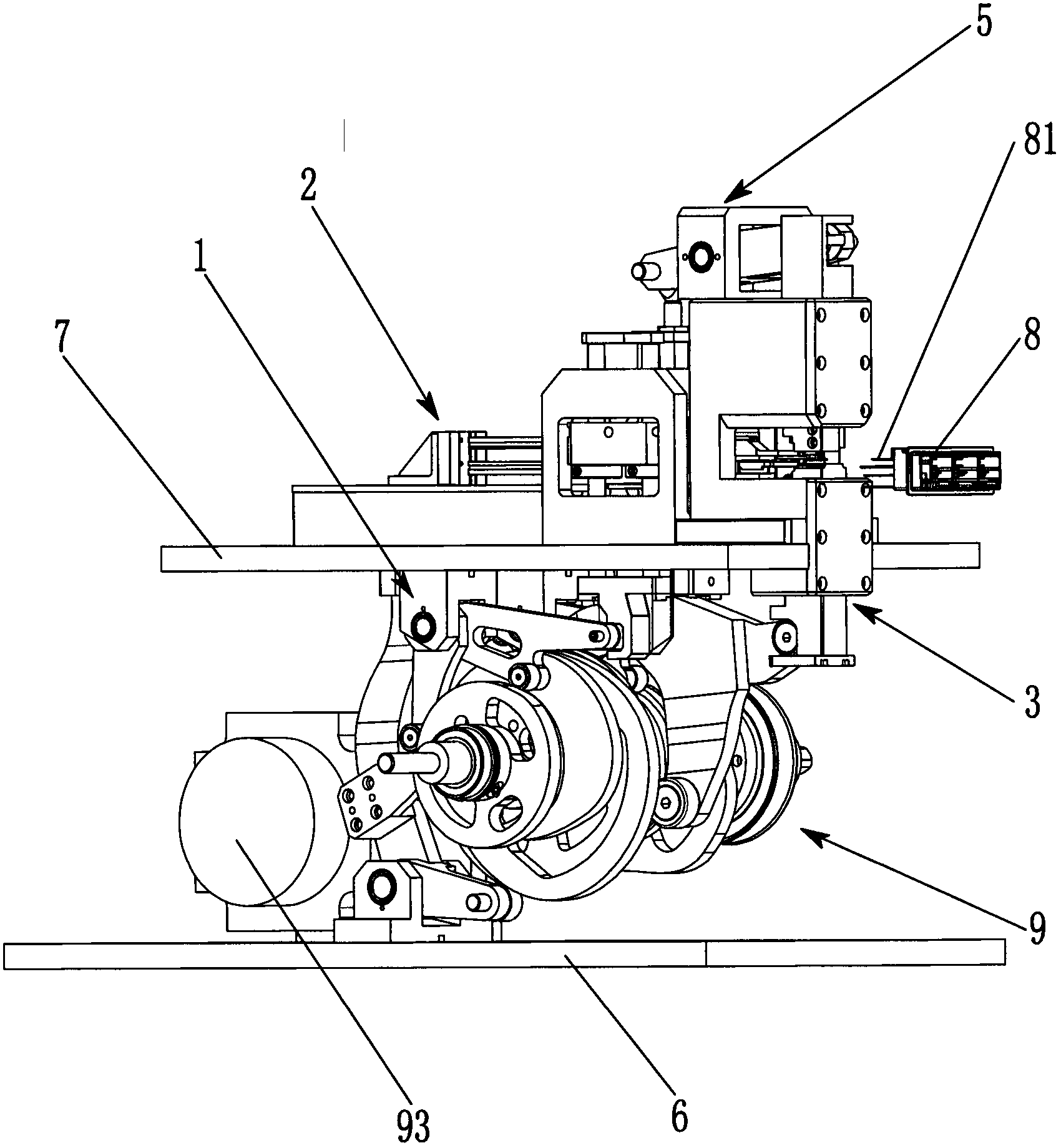
[0026] Such as figure 1 The shown terminal pin insertion device includes an upper clamping mechanism 1, a pin insertion mechanism 2, a lower cutting mechanism 3, a lower clamping mechanism 4, an upper cutting mechanism 5 and a cam driving mechanism 9, an upper clamping mechanism 1, a The needle mechanism 2, the lower cutting mechanism 3, the lower clamping mechanism 4, and the upper cutting mechanism 5 are sequentially connected by the cam driving mechanism 9, and these mechanisms are driven by the cam driving mechanism 9 to complete terminal cutting, terminal clamping, and terminal pin insertion in sequence. Actions.

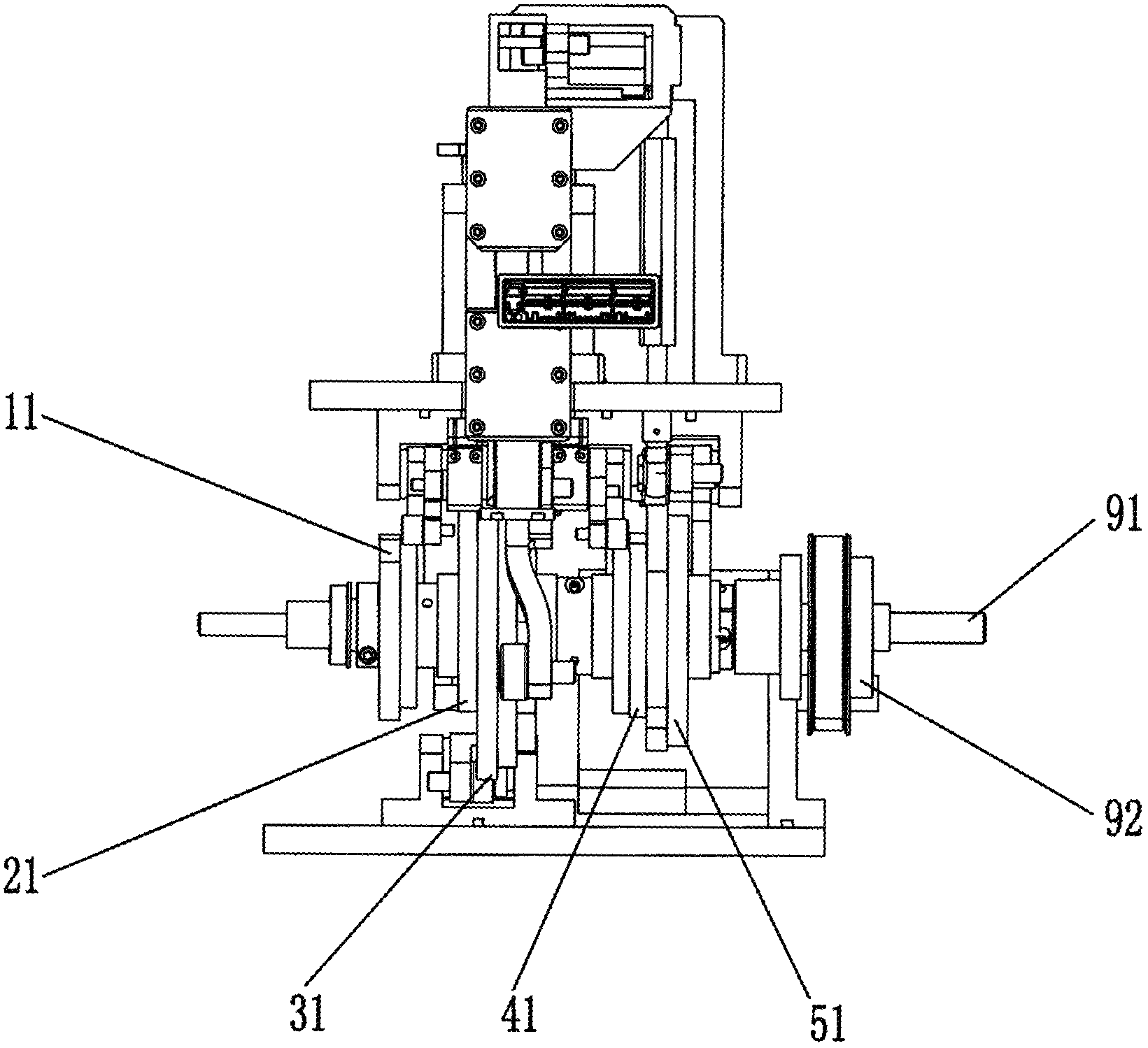
[0027] Such as figure 1 , figure 2 As shown, the cam drive mechanism 9 includes a motor 93, a transmission device and a cam drive sha...


PUM


Abstract

The invention provides a terminal pin plugging device which comprises an upper material clamping mechanism, a pin plugging mechanism, a lower cutting mechanism, a lower material clamping mechanism, an upper cutting mechanism and a cam drive mechanism, wherein the upper material clamping mechanism, the pin plugging mechanism, the lower cutting mechanism, the lower material clamping mechanism and the upper cutting mechanism are connected with one another through the cam drive mechanism in sequence and are driven by the cam drive mechanism to finish the actions of terminal cutting, terminal material clamping and terminal pin plugging. The terminal pin plugging device provided by the invention has the beneficial effects that the actions of terminal cutting, terminal material clamping and terminal pin plugging can be integrally finished, and the terminal pin plugging device has the advantages of high processing precision, quick speed and high production efficiency.

Description

technical field [0001] The invention relates to a processing equipment for terminal parts, in particular to a cam type terminal pin insertion device. Background technique [0002] In the field of terminal parts processing, the traditional method is generally to manually insert terminals into the workpiece. During manual processing, it is easy to cause terminal deformation, missing terminals, and irregular arrangement of inserted terminals, resulting in defective products. With the rapid growth of consumer electronics, automotive electronics, and communication terminal markets, connectors, as an indispensable part of electronic equipment, are also rapidly growing in demand. And because many products have to face smaller and lighter development, there are certain requirements for terminal spacing, appearance size, and height, which put forward higher requirements for the development and application of connectors towards miniaturization and high density. It is obvious that the...

Claims


Application Information

Patent Timeline
Patent Type & Authority Applications(China)
IPC IPC(8): H01R43/16H01R43/20
Inventor 陈雄斌
Owner SUZHOU HARMONTRONICS AUTOMATION TECH CO LTD
Why Eureka
Try Eureka