
Power supply equipment

A technology for power supply equipment and equipment, applied in electrical components, circuit devices, emergency power supply arrangements, etc., can solve the problems of expanding the space occupied by power supply equipment, increasing the cost of power supply equipment, etc., to reduce the space occupied and reduce costs.

Inactive Publication Date: 2012-10-03
HUAWEI TECH CO LTD
View PDF3 Cites 22 Cited by
  • Summary
  • Abstract
  • Description
  • Claims
  • Application Information

AI Technical Summary

Problems solved by technology

[0004] In the prior art, in order to realize the N+N backup of the DC / AC conversion unit, 2N corresponding AC / DC conversion units will be provided on the power supply equipment, and one input power supply will be connected to N AC / DC conversion units. , while the other input power supply is connected to other N AC / DC conversion units to convert AC power into DC power supply to supply power to the load. In each AC / DC conversion unit, multiple functional modules are set to realize AC to DC DC conversion, but the repeated setting of multiple functional modules not only expands the space occupied by the power supply equipment, but also increases the cost of the power supply equipment

Method used


Image

  • Power supply equipment
  • Power supply equipment
  • Power supply equipment

Examples


Embodiment 1

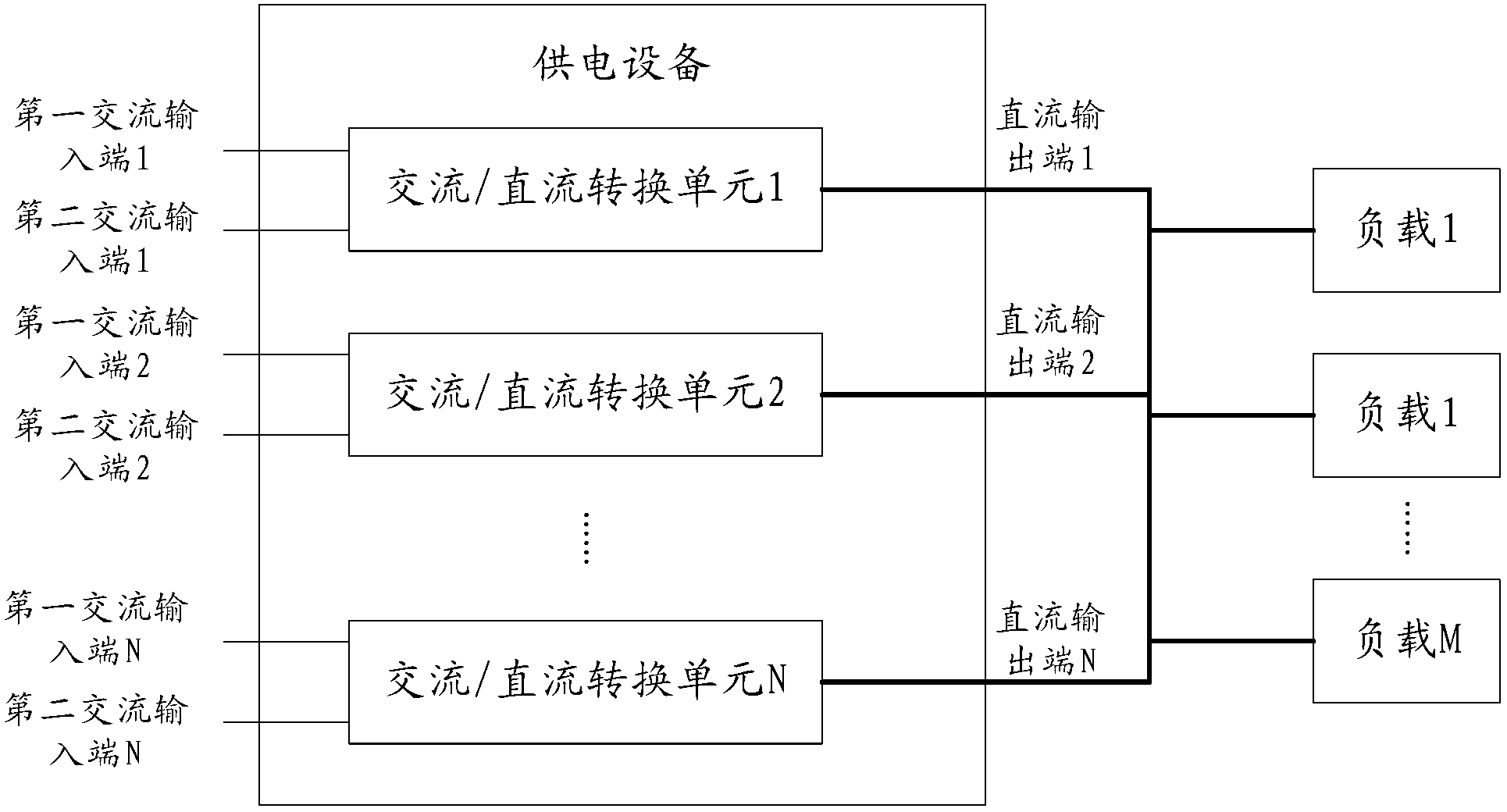
[0026] A power supply device, such as figure 1 The scenario shown includes: multiple AC / DC conversion units connected in parallel at the DC output end;

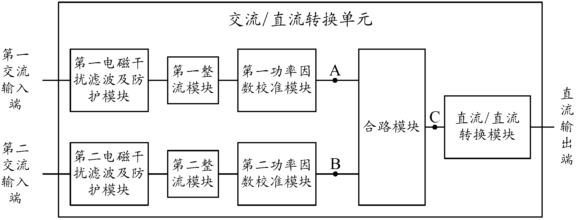
[0027] The AC / DC conversion unit, such as figure 2 shown, including:

[0028] The first AC input terminal, the first EMI filter and protection module, the first rectification unit and the first PFC module are connected in sequence;

[0029] A second AC input terminal, a second EMI filter and protection module, a second rectification module, and a second PFC module connected in sequence;

[0030] A combiner module, the combiner module is respectively connected to the first PFC module and the second PFC module;

[0031] A DC / DC conversion module is connected to the DC output terminal and the combining module;

[0032] The rectification module is used to rectify the input alternating current into direct current;

[0033] The PFC module is used to detect and eliminate the interference of high-frequency harmonics in the dire...

Embodiment 2

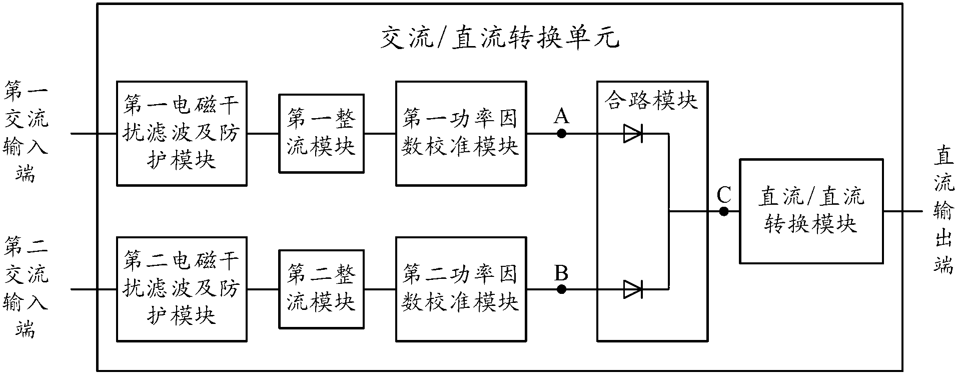
[0044] According to the scenario in which the power supply device in Embodiment 1 realizes the switching of the input AC power through the combining module, optionally, the combining module may be as follows image 3 shown, including:

[0045] Two diodes, the anodes of the two diodes are respectively connected to the first PFC module and the second PFC module, and the cathodes of the two diodes are connected to the DC / DC conversion module.

[0046] Taking an AC / DC conversion unit as an example to describe, when the voltage at point A is 312 volts and the voltage at point B is 310 volts, according to the unidirectional conduction characteristic of the diode, the diode connected to the first PFC module is turned on; , a voltage drop occurs on the diode connected to the first PFC module, for example, 1 volt, the voltage at point C is 311 volts; the voltage difference between point B and point C is less than 1 volt, and the diode corresponding to point B is turned off. off, only ...

Embodiment 3

[0051] According to the scenario in which the power supply device in Embodiment 1 realizes the switching of the input AC power through the combining module, optionally, the combining module may be as follows Figure 4 shown, including:

[0052] Two Metal-Oxide Semiconductor Field Effect Transistors (Metal-Oxide- Semiconductor Field-Effect Transistor, hereinafter referred to as MOSFET); the source and drain of the MOSFET are respectively connected to the PFC module and the DC / DC conversion module.

[0053] The power supply equipment includes:

[0054] A combination detection module, which is respectively connected to the first PFC module, the second PFC module and the DC / DC conversion module;

[0055] The combination control module is respectively connected to the combination detection module and the gates of the two MOSFETs.

[0056] To make the description clearer, an AC / DC conversion unit is taken as an example. When the power supply equipment starts to work, the combinin...


PUM


Abstract

The invention discloses power supply equipment, which belongs to the field of power supply and distribution. The power supply equipment is designed for solving the problems of larger occupied space and high cost the power supply equipment in the prior art. The power supply equipment comprises a plurality of alternating current / direct current conversion units of which the direct current output ends are connected in parallel, wherein each alternating current / direct current conversion unit comprises a first alternating current input end, a first electromagnetic interference filtering and protecting module, a first rectification unit, a first power factor correction module, a second alternating current input end, a second electromagnetic interference filtering and protecting module, a second rectification unit, a second power factor correction module and a combination module; the first alternating current input end, the first electromagnetic interference filtering and protecting module, the first rectification unit and the first power factor correction module are connected in sequence; the second alternating current input end, the second electromagnetic interference filtering and protecting module, the second rectification unit and the second power factor correction module are connected in sequence; the combination module is respectively connected with the first power factor correction module and the second power factor correction module; and a direct current / direct current conversion module is connected with the direct current output end and the combination circuit.

Description

technical field [0001] The invention relates to the field of power supply and distribution, in particular to a power supply device. Background technique [0002] In the field of communication technology, the work of information and communication equipment is inseparable from a stable power supply. The types of power used by information and communication equipment are divided into AC and DC. power supply. [0003] For information and communication equipment powered by AC power supply equipment, in order to improve the reliability of power supply, it is usually necessary to support 1+1 backup of input power (such as two-way AC power grid) and N+N backup of AC / DC conversion unit, that is, one The input power supplies power to N AC / DC conversion units, and the other input power supplies power to the other N AC / DC conversion units, so as to ensure that when one input power fails or one AC / DC conversion unit fails, the information and communication equipment can be normal. Work....

Claims


Application Information

Patent Timeline
IPC IPC(8): H02J9/06
CPCH02M1/00H02M7/23H02J9/06H02J5/00H02M1/4208H02J1/102Y02B70/10
Inventor 方庆银
Owner HUAWEI TECH CO LTD
Learn More