Permanent magnet motor rotor with excitation circuit variable reluctance and leakage flux path function

A technology of excitation circuit and permanent magnet motor, which is applied in the direction of magnetic circuit rotating parts, magnetic circuit shape/style/structure, etc., can solve the problems of permanent magnet motor weak field speed regulation and other problems, and achieve the effect of large output torque

Inactive Publication Date: 2012-10-03
HEILONGJIANG UNIV
View PDF4 Cites 18 Cited by
  • Summary
  • Abstract
  • Description
  • Claims
  • Application Information

AI Technical Summary

Problems solved by technology

[0003] The present invention aims to solve the problem of difficulties in field-weakening speed regulation of permanent magnet motors due to non-adjustable excitation in the existing field-weakening sp

Method used


Image

  • Permanent magnet motor rotor with excitation circuit variable reluctance and leakage flux path function
  • Permanent magnet motor rotor with excitation circuit variable reluctance and leakage flux path function
  • Permanent magnet motor rotor with excitation circuit variable reluctance and leakage flux path function

Examples


specific Embodiment approach 1

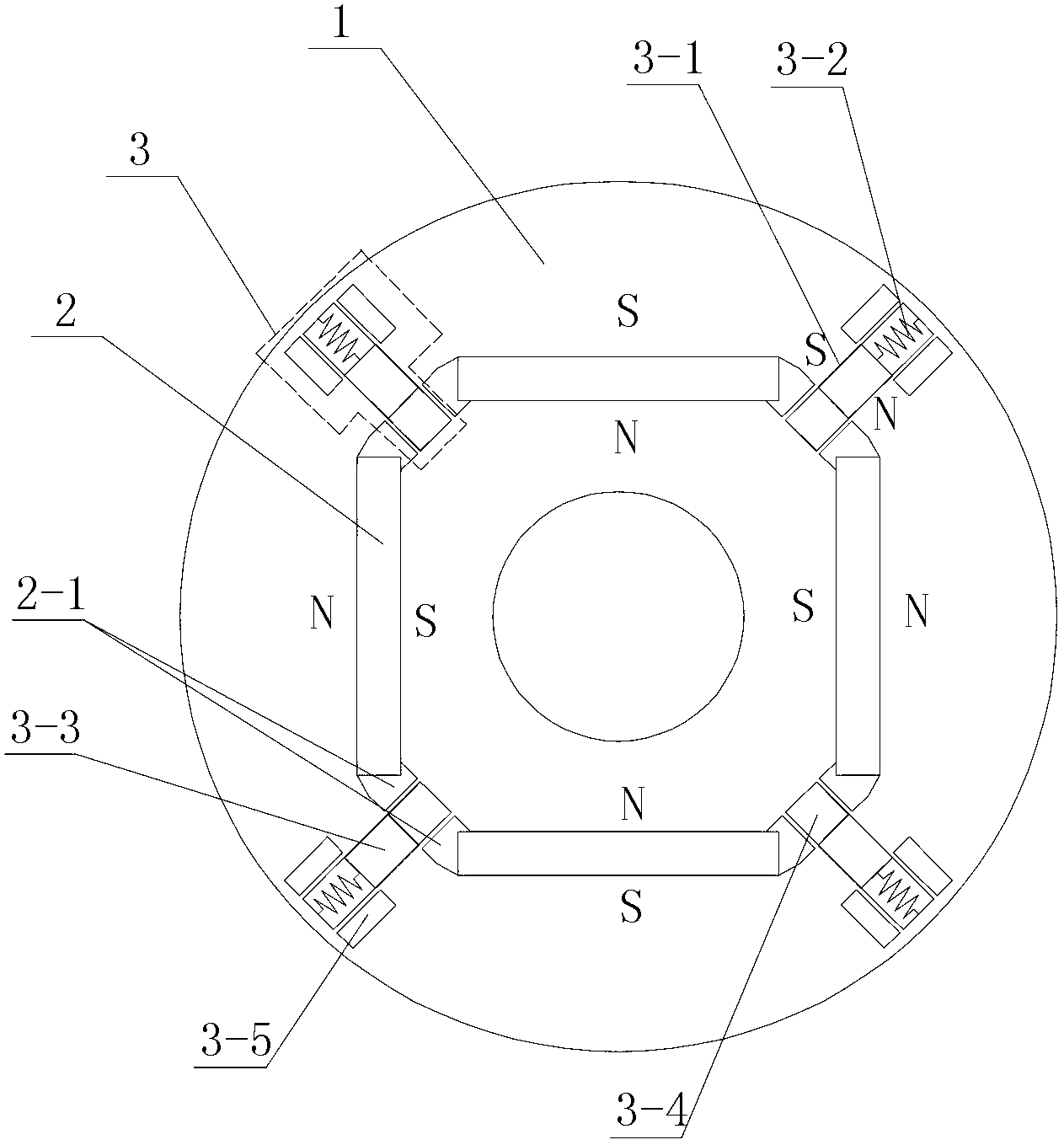
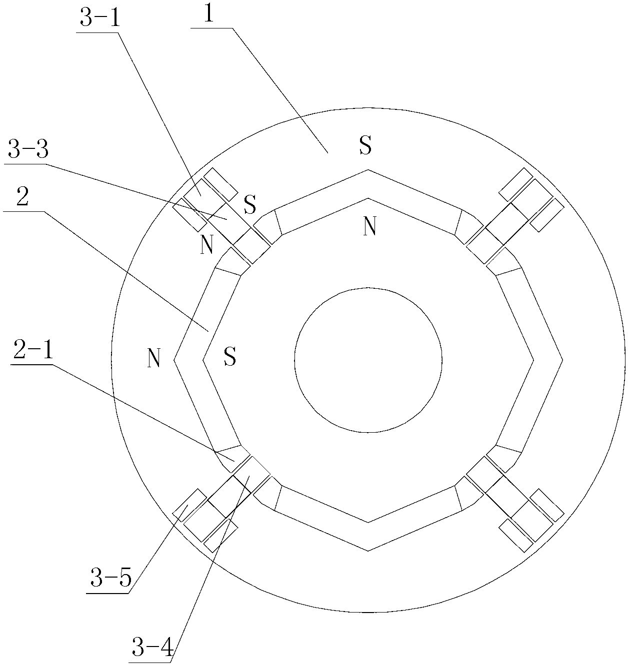
[0025] Specific implementation mode one: the following combination Figure 1 to Figure 4 Describe this embodiment, the permanent magnet motor rotor with the function of excitation circuit variable reluctance and flux leakage path described in this embodiment, it includes a rotor core 1, it also includes 2n main permanent magnets 2 and 2n field weakening units 3, n is a positive integer,

[0026] There are 2n through slots along the axial direction of the rotor core 1, and the 2n through slots are evenly distributed along the circumferential direction of the rotor core 1, and a main permanent magnet 2 with a matching shape is embedded in each through slot,

[0027] A field-weakening unit 3 is arranged between every two adjacent main permanent magnets 2 along the circumferential direction on the rotor core 1, and a magnetic isolation slot is provided between the two ends of the main permanent magnet 2 along the circumferential direction and the adjacent field-weakening units 3 ...

specific Embodiment approach 2

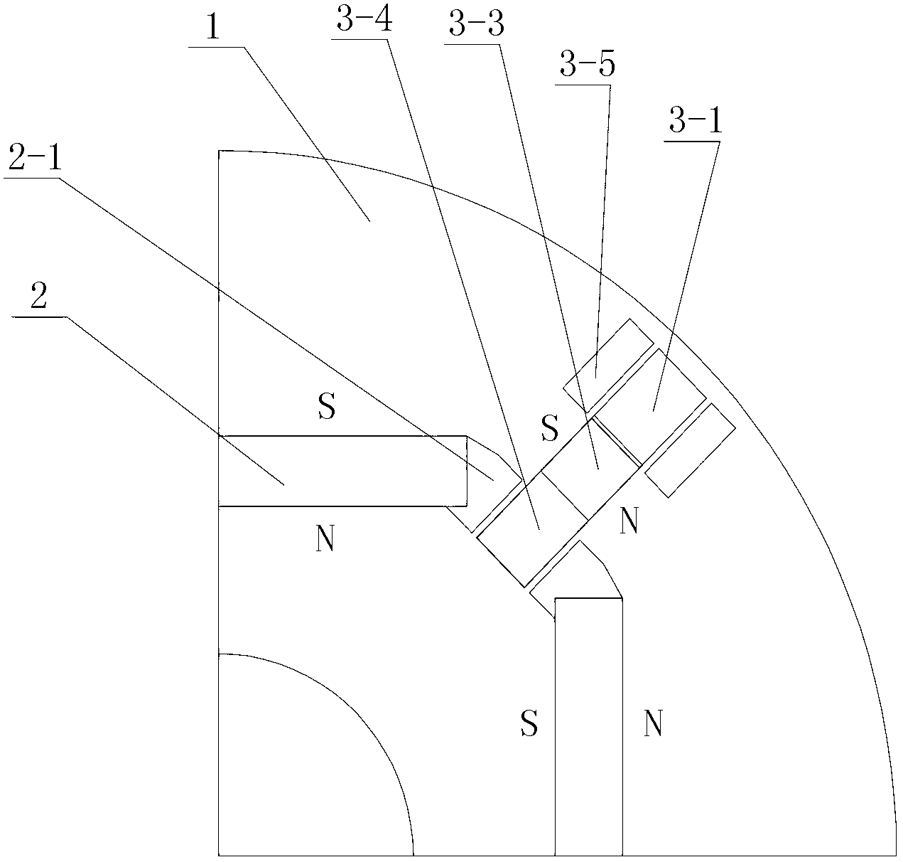
[0030] Specific implementation mode two: the following combination Figure 1 to Figure 4 Describe this embodiment. This embodiment is a further description of Embodiment 1. Each field weakening unit 3 includes a slide rail groove 3-1, a spring 3-2, an auxiliary permanent magnet 3-3, a magnetic block 3-4 and Two non-magnetic slots,

[0031] The slide rail groove 3-1 is arranged radially between the two main permanent magnets 2 on the rotor core 1, and the spring 3-2, the auxiliary permanent magnet 3-3 and the magnetic guide block 3-4 are arranged radially from outside to inside The cloth is arranged in the slide rail groove 3-1, the fixed end of the spring 3-2 is fixedly connected with the groove bottom of the slide rail groove 3-1, and the free end of the spring 3-2 is fixedly connected with one end of the auxiliary permanent magnet 3-3, The other end of the auxiliary permanent magnet 3-3 is fixedly connected to the magnetic permeable block 3-4; the radial length of the magne...

specific Embodiment approach 3

[0039] Specific implementation mode three: the following combination Figure 1 to Figure 4 Describe this embodiment, this embodiment is a further description of Embodiment 2, the field weakening unit 3 also includes two non-magnetic permeable blocks 3-5, each non-magnetic permeable block 3-5 is embedded in a non-magnetic permeable slot .

[0040] The non-magnetic conductive block 3-5 can be a non-magnetic conductive metal body, and the shape of the non-magnetic conductive block 3-5 can be set as rectangle, square, triangle or trapezoid as required.

[0041] When the motor system where the rotor core 1 is located is running at or below the base speed, the magnetic block 3-4 and the auxiliary permanent magnet 3-3 are stationary and do not move, and the highest point of the radial height of the auxiliary permanent magnet 3-3 is lower than the non- The height of the lowest radial point of the magnetic block 3-5. At this time, the auxiliary permanent magnet 3-3 in the slide rail ...


PUM


Abstract

The invention discloses a permanent magnet motor rotor with an excitation circuit variable reluctance and leakage flux path function, which belongs to the technical field of the motor and solves the problem that in the weak magnet speed regulation technology of the traditional synchronous permanent magnet motor, the permanent magnet motor is difficult in weak magnet speed regulation because excitation can not be regulated. The permanent magnet motor rotor with the excitation circuit variable reluctance and leakage flux path function comprises a rotor iron core, 2n main permanent magnets and 2n weak magnet units, wherein n is a positive integer; 2n trough slots are arranged along the axial direction of the rotor iron core and are evenly distributed along the peripheral direction of the rotor iron core; one main permanent magnet with a shape matched with the shape of each through slot is respectively embedded in each trough; a weak magnet unit is arranged between every two adjacent main permanent magnets along the peripheral direction of the rotor iron core; magnetic isolation grooves are arranged among two ends of the main permanent magnets along the peripheral direction and the adjacent weak magnet units; the main permanent magnet adopts radial magnetization; and the magnetization directions of the adjacent main permanent magnets are opposite. The invention is suitable for the permanent magnet motor.

Description

technical field [0001] The invention relates to a permanent magnet motor rotor with the functions of variable reluctance of an excitation circuit and a flux leakage path, and belongs to the technical field of motors. Background technique [0002] The excitation of the permanent magnet synchronous motor cannot be adjusted, and the field weakening control must be carried out when it runs above the base speed. In the traditional method, by increasing the negative direct-axis demagnetization current, the demagnetization effect of the armature reaction is used to weaken the air gap magnetic field of the motor, which is equivalent to directly weakening the excitation magnetic field to achieve the purpose of weakening the field speed. This method of field-weakening speed-up will increase the current of the motor and reduce the efficiency of the system, which limits the application range of the permanent magnet synchronous motor. In addition, in the permanent magnet synchronous mot...

Claims


Application Information

Patent Timeline
IPC IPC(8): H02K1/27
Inventor 李春艳寇宝泉李春红张立富
Owner HEILONGJIANG UNIV
Why Eureka
Try Eureka