Indoor locating method, data acquisition method and data acquisition system
A technology for indoor positioning and data collection, applied in electrical components, wireless communication, etc., can solve problems such as time-consuming, manpower-consuming, and large-scale use, and achieve the effect of effective indoor positioning and convenient data collection
- Summary
- Abstract
- Description
- Claims
- Application Information
AI Technical Summary
Problems solved by technology
Method used
Image

Examples
Embodiment 1
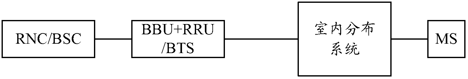
[0038] figure 1 It is a system architecture diagram of a typical indoor coverage system. Such as figure 1 As shown, it includes a base station, an indoor distribution system, and a mobile station (Mobile Station, MS), where the base station includes, for example, a radio network controller (Radio Network Controller, RNC) / base station controller (Base Station Controller, BSC), and baseband processing Unit (Building Baseband Unit, BBU) and remote radio unit (Remote Radio Unit, RRU), or base transceiver station (Base Transceiver Station, BTS) instead of baseband processing unit (BBU) and remote radio unit, MS such as mobile phone . During the downlink communication, the base station sends downlink signals to the indoor distribution system, and the indoor distribution system sends the downlink signals to the MS; during the uplink communication, the MS sends uplink signals to the indoor distribution system, and the indoor distribution system sends the uplink signals to the MS. t...
Embodiment 2
[0057] On the basis of Embodiment 1, in this embodiment, the step of sending the pseudo-carrier patrol to the remote units within the preset range specifically includes:
[0058] According to the patrol routing table, the remote unit of the current patrol is determined, and the pseudo carrier is sent to the remote unit of the current patrol.
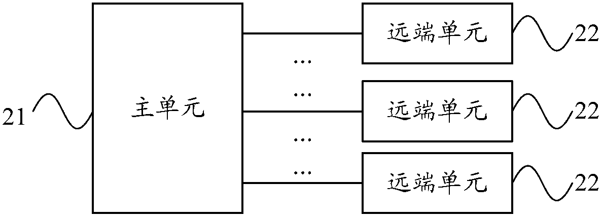
[0059] In this embodiment, taking the indoor distribution system further including an expansion unit as an example, the steps of obtaining the patrol routing table are described. Wherein, the expansion unit is arranged between the main unit and the remote unit, forming a structure in which the main unit is connected to one or more expansion units, and each expansion unit is connected to one or more remote units.
[0060] The steps for obtaining the patrol routing table include, for example:
[0061] Obtain the optical fiber interface of the main unit, and establish a first-level interface table including the optical fiber interface;
...
Embodiment 3
[0073] On the basis of any of the above embodiments, the sending the pseudo-carrier patrol to the remote units within the preset range specifically includes:
[0074] Sending the pseudo-carrier to the remote units within the preset range in rounds in the form of digital signals and / or analog signals;
[0075] Correspondingly, the polling sending is realized by controlling the logic switch array and / or controlling the single-pole multi-throw switch.
[0076] Specifically, the indoor positioning system used to implement the indoor positioning method in any of the foregoing embodiments may be a digital system, an analog system, or a system combining digital and analog. In the following, the signal processing methods in the indoor positioning system will be described in detail for these three situations respectively.
[0077] Scenario 1: The indoor positioning system is a fully digital distribution system
[0078] Figure 5 It is a system architecture diagram of the indoor posi...
PUM
 Abstract
Description
Claims
Application Information
 - R&D
- Intellectual Property
- Life Sciences
- Materials
- Tech Scout
- Unparalleled Data Quality
- Higher Quality Content
- 60% Fewer Hallucinations
Browse by: Latest US Patents, China's latest patents, Technical Efficacy Thesaurus, Application Domain, Technology Topic, Popular Technical Reports.
© 2025 PatSnap. All rights reserved.Legal|Privacy policy|Modern Slavery Act Transparency Statement|Sitemap|About US| Contact US: help@patsnap.com