Light-emitting diode (LED) driving system

A technology of LED driving, rectifying and filtering circuit, applied in the field of LED lighting, can solve the problems of difficult to realize driving circuit, inability to miniaturize, complicated circuit, etc., and achieve the effect of reducing EMI radiation, simple circuit and high power factor

Active Publication Date: 2012-10-03
SUPEC SUZHOU
View PDF4 Cites 8 Cited by
  • Summary
  • Abstract
  • Description
  • Claims
  • Application Information

AI Technical Summary

Problems solved by technology

However, the disadvantages of this method are: complex circuit, many devices used, high cost, inabi

Method used


Image

  • Light-emitting diode (LED) driving system

Examples


Example Embodiment

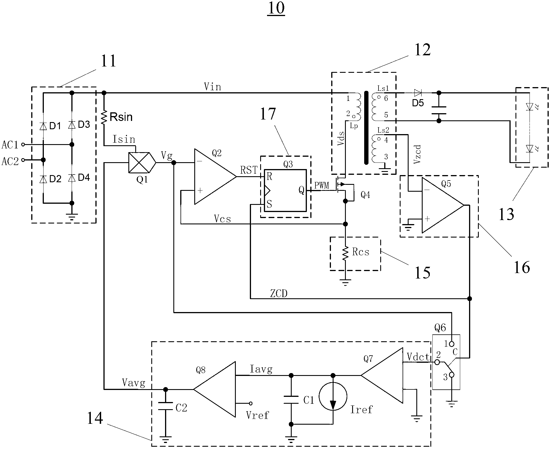
[0028] The specific embodiment of the present invention discloses an LED driving system, including:

[0029] Rectifier filter circuit;

[0030] A voltage conversion circuit connected to the rectification filter circuit, the voltage conversion circuit having a primary winding, a first secondary winding, and a second secondary winding, the primary winding receives the output voltage of the rectification filter circuit, the first The secondary winding outputs a secondary current to the LED load;

[0031] A first switch, the first switch is a power MOS tube, the drain of which is connected to the primary winding;

[0032] A primary-side sampling network, which is connected to the source of the first switch and generates a primary induced voltage when the first switch is turned on;

[0033] A driving pulse generating module, which generates a switch signal to control the gate voltage of the first switch;

[0034] A zero-crossing detection module, the input terminal of which is connected to t...


PUM


Abstract

The application discloses a light-emitting diode (LED) driving system comprising a rectifier filter circuit, a voltage conversion circuit which is connected with the rectifier filter circuit, a first switch, an original edge sampling network, a driving pulse generation module, a zero-crossing detection module, an average current ring, a multiplier, a second switch and a comparator, wherein when the level of the second switch at the output end of the zero-crossing detection module is low, the output end of the multiplier is connected to the input end of the average current ring. According to the LED driving system, not only can the average output of constant current and higher power factor be realized, but also the driving system can be directly arranged in an LED lamp cap because no coupler is needed to feed back the measured current, the circuits are simple, devices are few, the cost is low and the size is small.

Description

technical field [0001] The present application belongs to the field of LED lighting, and in particular relates to an LED driving system. Background technique [0002] The light characteristics of LED (Light Emitting Diode, light-emitting diode) are usually described as a function of current, not a function of voltage. A small change in the forward voltage drop of the LED will cause a large change in the LED current, thereby causing a large change in brightness . Therefore, the constant voltage source drive cannot guarantee the consistency of the LED brightness, and affects the reliability, life and light decay of the LED. Therefore, LEDs are usually driven by a constant current source. In addition, some civilian products such as mobile phone chargers must also have a constant current output function. [0003] The current latest "Energy Star" specification requires that all external electrical equipment use PFC above 75W. The latest specification in the field of lighting ...

Claims


Application Information

Patent Timeline
IPC IPC(8): H05B37/02
Inventor 范立新
Owner SUPEC SUZHOU
Why Eureka
Try Eureka