Beam of steel plate straightener

A technology of straightening machine and crossbeam, which is applied in the field of steel strip straightening machine, can solve problems such as difficult structural design, limited adjustment amount, complex motion mechanism, etc., and achieve the effect of eliminating the bouncing phenomenon

Inactive Publication Date: 2012-10-10
TAIYUAN UNIVERSITY OF SCIENCE AND TECHNOLOGY +1
View PDF4 Cites 6 Cited by
  • Summary
  • Abstract
  • Description
  • Claims
  • Application Information

AI Technical Summary

Problems solved by technology

However, its defect is that the preset bending deformation of the straightening roller is a certain value, while the deflection and deformation of the beam during the production process of the straightening machine is a variable value, and the two cannot be completely offset. In addition, the above two methods also have some differences. Disadvantages are: (1) The split-beam type bending roll structure has a large structure and complex motion mechanism, which consumes more steel, which brings difficulties to other structural designs, and the length-to-height ratio of the beam is close to 1. It is not suitable to use in the middle; ② wedge-type bending roll structure, due to the limitation of the structure size and the self-locking function of the wedge, the adjustment amount is limited, and it is also not suitable for occasions with large deflection and deformation of the beam

Method used


Image

  • Beam of steel plate straightener
  • Beam of steel plate straightener

Examples


Embodiment Construction

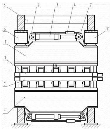
[0010] Such as figure 2 As shown, the steel plate straightening machine includes a frame 5, left and right pressing devices 6, 6', upper and lower beams 1, 1', and upper and lower roller systems 7, 7'.

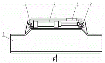
[0011] Taking the upper beam 1 of the steel plate straightening machine as an example, during the production of the steel plate straightening machine, the straightening force F The upper roller system 7 acts on the lower bearing surface of the upper beam 1, forcing the upper beam to produce upward convex negative bending deflection deformation f At this time, the sensor 4 installed on the upper beam 1 detects the deformation signal of the upper beam 1 and transmits it to the tension PID controller to control the hydraulic cylinder 3 to apply a tension on the left and right supports 2, 2' N , forcing the beam to produce positive bending deflection deformation δ . Deformation due to positive bending deflection δ The deformation direction of the beam and the negative bend...


PUM


Abstract

The invention relates to a beam of a steel plate straightener, and belongs to the technical field of steel strip straighteners. The beam is characterized in that the upper surfaces of the left end and the right end of an upper beam are fixedly and integrally connected with a left support and a right support respectively in a welding manner, a sensor and a hydraulic cylinder are mounted between the left support and the right support, the sensor is electrically connected with a tension PID (proportion integration differentiation) controller, the hydraulic cylinder is controlled by the tension PID controller, and the bottom end of the hydraulic cylinder and the top end of a piston rod are hinged to the left support and the right support respectively. The structure of a lower beam is as same as that of the upper beam, and the mounting direction of the lower beam is opposite to that of the upper beam. The beam has the advantages that flexible deformation of the upper beam and the lower beam in loading can be eliminated, and bounce in change of working load can also be eliminated.

Description

technical field [0001] The invention belongs to the technical field of a steel plate straightening machine, and in particular relates to a beam of a steel plate straightening machine. Background technique [0002] At present, during the straightening production process of the steel plate leveling machine, the upper and lower beams will produce a certain elastic deflection deformation under the action of the straightening force, resulting in serious unevenness in the roll gap of the straightening roller along the width direction of the plate, and the roll gap on both sides The phenomenon of small and large middle roll gap will lead to poor straightening quality. [0003] In order to overcome the influence of the above factors, there are two compensation methods used in the prior art, ① using the split beam bending roll structure, ② using the wedge type bending roll structure, these two methods are for the straightening roll of the straightening machine A bending deformation ...

Claims


Application Information

Patent Timeline
Patent Type & Authority Applications(China)
IPC IPC(8): B21D1/02
Inventor 袁文旭周存龙李林郝建军申宝成申竹茂
Owner TAIYUAN UNIVERSITY OF SCIENCE AND TECHNOLOGY
Why Eureka
Try Eureka