Construction method of anti-bending reinforced floor structure

A construction method and technology for reinforcing plates, which are applied in building construction, building maintenance, construction, etc., can solve problems such as poor reinforcement effect, difficult construction, and inconvenient maintenance, and achieve low construction difficulty, reduced material costs, and reduced manpower. cost effect

Inactive Publication Date: 2020-06-09
TONGJI UNIV ARCHITECTURAL DESIGN INST GRP CO LTD
View PDF13 Cites 0 Cited by
  • Summary
  • Abstract
  • Description
  • Claims
  • Application Information

AI Technical Summary

Problems solved by technology

[0006] Based on this, it is necessary to provide a construction method for bending-resistant and reinforced floor slab structures in view of the problems of poor reinforcement effect, difficult construction, high cost and inconvenient maintenance of traditional floor reinforcement methods

Method used


Image

  • Construction method of anti-bending reinforced floor structure
  • Construction method of anti-bending reinforced floor structure
  • Construction method of anti-bending reinforced floor structure

Examples


Embodiment 1

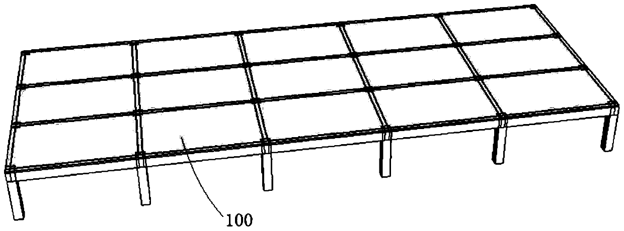
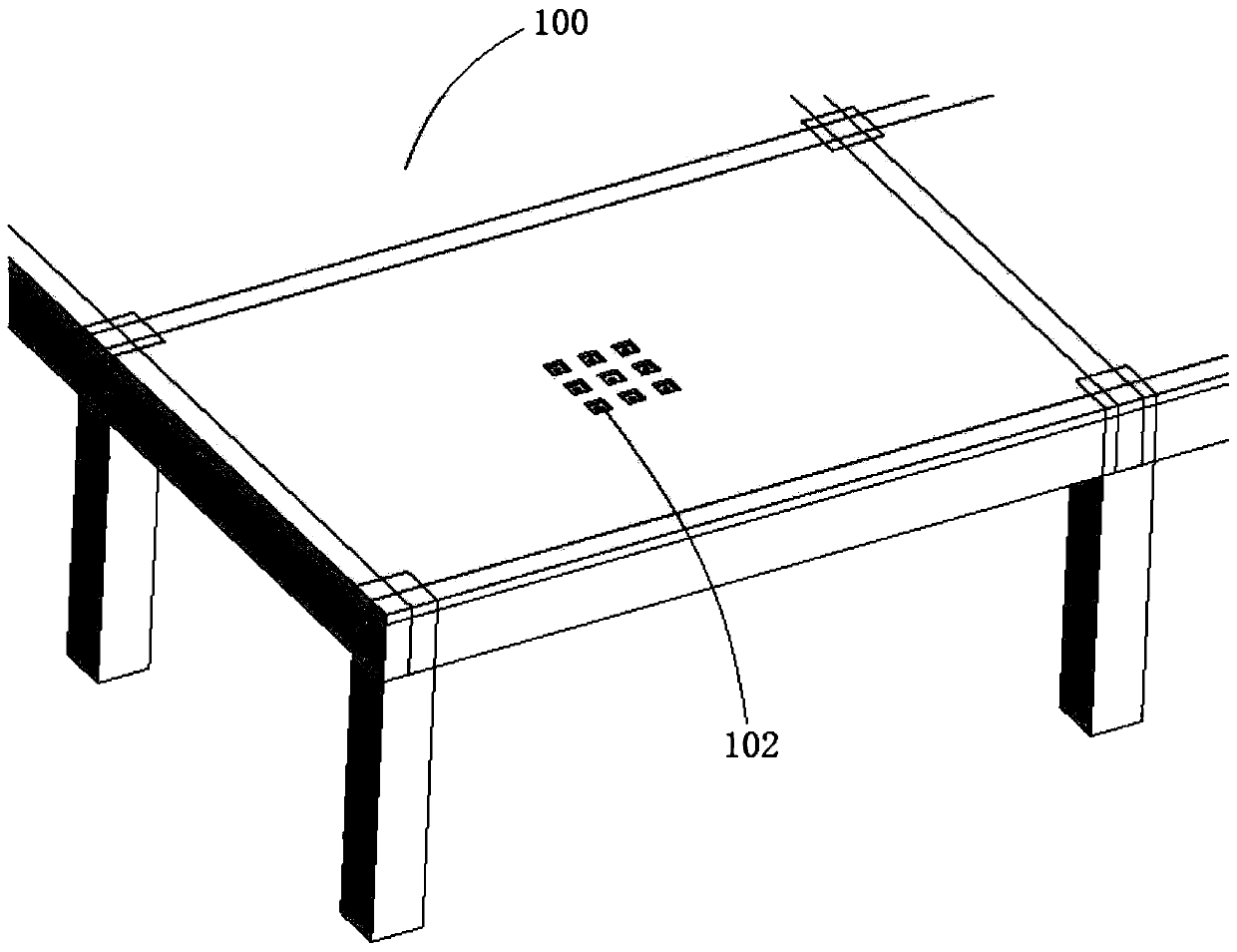
[0050] In Embodiment 1, the fixing hole is a fixing through hole 101 penetrating through the two sides of the floor main body 100, and the shear connector 210 is inserted into the fixing through hole 101 from below, so that the reinforcing body 200 fixed at figure 1 and figure 2 The lower surface of the floor body 100 is shown.

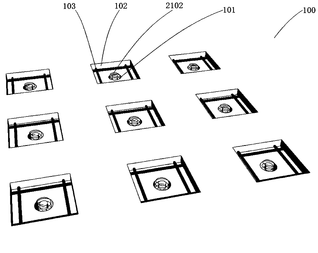
[0051] In Example 1, refer to Figure 4 , the reinforcing body 200 includes a plurality of reinforcing plates 201 , and the plurality of reinforcing plates 201 are arranged vertically and horizontally in the middle of the lower surface of the floor main body 100 . Reinforcement plates 201 arranged vertically and horizontally form a mesh reinforcement surface, which can bear most of the weight and load of the floor main body 100 from below, thus effectively strengthening the floor; meanwhile, the middle part of the floor main body 100 bears a larger load than the edge parts More concentrated, the net-shaped reinforcing plate 201 can directly support ...

Embodiment 2

[0066] Such as Figure 6 In the second embodiment shown, the fixing hole is a fixing counterbore 101' provided on the installation side of the floor main body 100', and the shear connector 210' is inserted into the fixing counterbore 101', so that The reinforcing body 200' is fixed on the installation side.

[0067] It should be noted that the installation side of the second embodiment can be the upper surface of the middle span 110' of the floor main body 100', or the outer surface of the side span 120' of the floor main body 100'.

[0068] For ease of understanding, the reinforcing body 200 ′, the shear connector 210 ′ and the bonding body 300 ′ used in the second embodiment are the same as those in the first embodiment. Next, taking the construction on the upper surface of the mid-span 110' of the floor main body 100' as an example, the specific construction method is described as follows:

[0069] (1) The concrete on the upper surface of the floor main body 100' is chise...


PUM


Abstract

The invention relates to a construction method of an anti-bending reinforced floor structure. The construction method comprises the steps that fixing holes are formed in the surface of a floor main body; shear connectors are mounted on a reinforcing body, and the shear connectors are placed into the fixing holes, so that the reinforcing body is fixed on the surface of the floor main body; the floor main body is lifted to return to an initial deformation state; and bonding bodies are filled in gaps between the hole walls of the fixing holes and the shear connectors, so that the reinforcing bodyis fixedly connected with the floor main body. According to the construction method, the problems of shear bonding and coordinated deformation between the reinforcing body and the existing floor structure are solved by adopting the shear connectors, the integral firm connection between the reinforcing body and the original structural floor main body is achieved by arranging the shear connectors on the reinforcing body and by utilizing a bonding body connection manner, the reinforcing body and the floor main body are combined to completely form a whole, and when the horizontal force is borne,shearing and coordinated deformation can be resisted, so that the anti-bending reinforcement of the original structural floor main body is realized.

Description

technical field [0001] The invention relates to the field of architectural design and construction, in particular to a construction method for bending-resistant and reinforced floor slab structures. Background technique [0002] Floor slabs in large buildings are prone to deformation and bending due to large loads during use, so it is necessary to strengthen the floor slabs in advance against bending. [0003] At present, there are two main solutions for floor reinforcement: 1) Enlarging section method: bonding the post-reinforcement structure with the existing floor structure through fine stone concrete or mortar; 2) Using chemical structural adhesive to bond carbon fiber cloth, Steel plates etc. are directly adhered to the floor surface. [0004] When the reinforced section method is adopted, the bond between the post-reinforced structure and the existing floor structure is not strong. The coordinated deformation ability of the existing floor structure is not good; in ad...

Claims


Application Information

Patent Timeline
Patent Type & Authority Applications(China)
IPC IPC(8): E04G23/02
CPCE04G23/0237
Inventor 贾远林
Owner TONGJI UNIV ARCHITECTURAL DESIGN INST GRP CO LTD
Why Eureka
Try Eureka