Follower rotary valve for plane oil distribution

An oil distribution and follow-up technology, which is applied in the direction of machines/engines, liquid fuel engines, fluid pressure actuators, etc., can solve problems affecting normal operation and safety, low efficiency, and high cost, so as to improve reliability and oil distribution The effect of high efficiency, simple overall structure and long service life

Active Publication Date: 2012-10-10
云霄县食品快检中心
View PDF11 Cites 13 Cited by
  • Summary
  • Abstract
  • Description
  • Claims
  • Application Information

AI Technical Summary

Problems solved by technology

Many companies at home and abroad are doing research on it. In terms of oil distribution methods for double-acting plunger motors (pumps), the main ones that have been realized are cam follower mechanism driving spool valve for reversing oil distribution, electric control spool valve for reversing oil distribution. , follower shaft oil distribution and other technologies, but the above-mentioned mechanisms all have their major disadvantages: the oil distribution method of the spool valve is theoretically feasible, but due to the reliability defects of the spool valve itself (such as prone to jamming , fatigue damage, etc.) will affect the reliability of the double-acting piston motor (pump), once one of the slide valves fails, it will affect the normal operation and safety of the entire motor (pump) mechanism, and, since each piston needs to be equipped with The cost of one or two spool valves is also high, and the leakage of multiple spool valves is accumulated, and the efficiency is also very low; although the follower shaft oil distribution scheme solves some reliability problems of spool valve oil distribution, due to Gap compensation cannot be realized, and long-term wear will increase the gap and affect efficiency

Method used


Image

  • Follower rotary valve for plane oil distribution
  • Follower rotary valve for plane oil distribution
  • Follower rotary valve for plane oil distribution

Examples


Embodiment 1

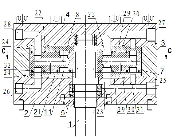
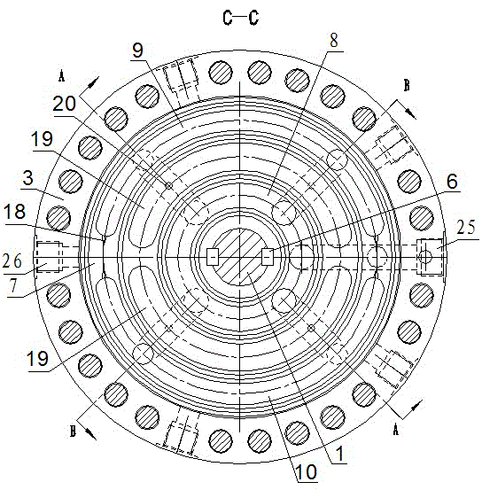
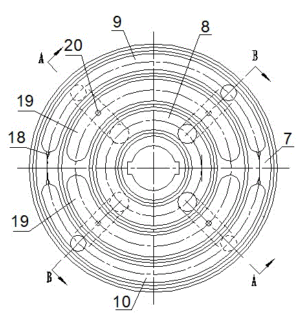
[0025] Such as Figure 1 to Figure 5 As shown, the follow-up rotary valve with plane oil distribution in this embodiment includes a central shaft 1, an end cover 2 fixedly connected by several bolts, a valve body 3 and a bottom cover 4, and the inner end of the central shaft 1 is installed through a bearing 5. In the end cover 2, the valve body 3 and the bottom cover 4, the outer end of the central shaft 1 is provided with a structure for transmitting torque such as a keyway, and a valve core 7 is provided on the central shaft 1 in the valve body 3 through a transmission key 6. The upper end surface of the spool 7 is provided with an annular groove 8 and two symmetrically distributed arc-shaped oil distribution grooves 9, 10, and the lower end surface of the spool 7 is provided with an annular groove 11 and two symmetrically distributed arc-shaped oil distribution grooves. Oil grooves 12 and 13, the two oil distribution grooves 9 and 12, 10 and 13 on both ends have the same ph...

Embodiment 2

[0031] Such as Figure 6 As shown, the difference between this embodiment and Embodiment 1 is: on the adjacent end surfaces of the end cover 2 and the floating side plate 21, on the adjacent end surfaces of the bottom cover 4 and the adjacent floating side plate 22, both There is a compensation pressure oil chamber 33, and a sealing sleeve 34 is arranged in the compensation pressure oil chamber 33, and a sealing ring is provided between the sealing sleeve 34, the end cover 2 and the side wall of the floating side plate 21, and a sealing ring is arranged between the sealing sleeve 34 and the bottom A sealing ring is also provided between the cover 4 and the side wall of the floating side plate 22; between the connecting oil holes 24 of each floating side plate 21, 22 and the two ends of the internal oil passage of the end cover 2 or the bottom cover 4, a sealing ring is provided. There is a positioning cavity, and a positioning sleeve 35 is arranged in the positioning cavity, b...


PUM


Abstract

The invention discloses a follower rotary valve for plane oil distribution. The follower rotary valve comprises a central shaft, an end cover, a valve body and a bottom cover, wherein the end cover, the valve body and the bottom cover are fixedly connected, the central shaft in the valve body is provided with a valve core through a driving key, the two end faces of the valve core are respectively provided with a ring slot and two symmetrically-distributed circular arc distributing grooves, each ring slot is connected with a distributing groove on each of the two end faces through an internal oil channel, the two ring slots are connected with different two distributing grooves, and two distributing grooves connected with the same ring slot are arranged on the two sides of the central shaft; the parts (on both sides of the valve core) of the central shaft are slipperily provided with a floating side plate, and a connecting oil channel and a plurality of connecting oil holes are formed in each floating side plate; the end cover and the bottom cover are respectively provided with an oil port and a plurality of working ports, and the oil port is connected with the ring slots on the adjacent end faces of the valve core respectively through the internal oil channel and the connecting oil channel in an adjacent floating side plate; and an ring-shaped pressure compensation oil cavity is arranged between the end cover and the adjacent floating side plate. The valve disclosed by the invention has the advantages of good followability, high reliability, high oil distribution efficiency and long service life and the like.

Description

technical field [0001] The invention relates to a follow-up rotary valve for distributing oil to a hydraulic double-acting plunger motor or pump. Background technique [0002] Traditional plunger motors (pumps) are mostly single-acting functions, that is, their pistons only perform work when they move in one direction, while double-acting plunger motors have higher power density and obvious advantages due to the characteristics of pistons acting in both directions. The double-acting plunger motor itself is a relatively cutting-edge research topic. Since the reliability of the oil distribution mechanism of the double-acting plunger motor (pump) directly affects whether the motor or pump can work normally and work efficiency, a reliable oil distribution mechanism is One of the major difficulties. Many companies at home and abroad are doing research on it. In terms of oil distribution methods for double-acting plunger motors (pumps), the main ones that have been realized ar...

Claims


Application Information

Patent Timeline
Patent Type & Authority Applications(China)
IPC IPC(8): F04B53/10F15B13/02
Inventor 王利陈斌
Owner 云霄县食品快检中心
Why Eureka
Try Eureka