Anti-smudginess inserted vortex shedding flowmeter

A vortex flowmeter, plug-in technology, applied in the direction of volume measurement, liquid/fluid solid measurement, volume/mass flow generated by mechanical effects, etc., can solve the problems affecting the working efficiency of the flowmeter

Active Publication Date: 2012-10-10
GL TECH CO LTD
View PDF8 Cites 6 Cited by
  • Summary
  • Abstract
  • Description
  • Claims
  • Application Information

AI Technical Summary

Problems solved by technology

[0006] The purpose of the present invention is to provide an anti-dirty plug-in vortex flowmeter to solve the technical problem that the vortex flowmeter in the prior art requires frequent replacement of filter elements and affects the working efficiency of the flowmeter

Method used


Image

  • Anti-smudginess inserted vortex shedding flowmeter

Examples


Embodiment Construction

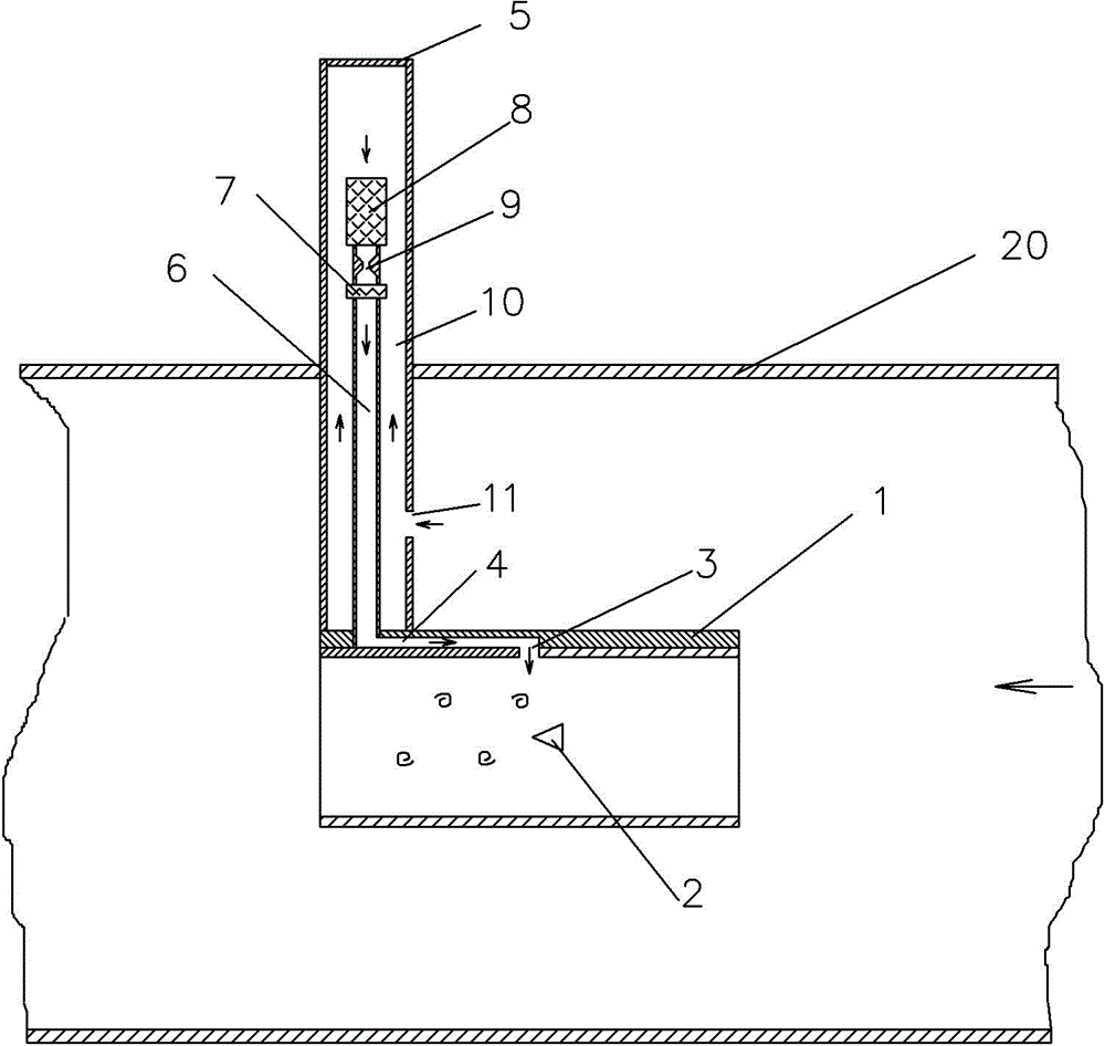
[0019] Such as figure 1 As shown, an embodiment of an anti-dirty plug-in vortex flowmeter, the vortex flowmeter in this embodiment includes a cylindrical measuring head 1 with fluid passages open at both ends, in the middle of the measuring head 1 A vortex generating body 2 with a small end facing the rear of the measuring head is fixed at the axis, and a pressure tapping port 3 is opened on the inner wall of the corresponding vortex generating body of the measuring head 1 . The measuring head 1 is fixed with an inner conduit 6 extending radially upwards above the measuring head, the central axis of the inner conduit 6 is perpendicular to the central axis of the vortex generating body 2, and the inner conduit 6 is located on the measuring head 1 At the rear of the pressure tapping port 3, the measuring head 1 is provided with a connecting channel 4 that communicates with the inner conduit 6 and the pressure tapping port 3 and is located behind the pressure tapping port. The co...


PUM


Abstract

The invention discloses an anti-smudginess inserted vortex shedding flowmeter which comprises a measuring head internally provided with a fluid passageway. A vortex generating body is fixedly arranged in the measuring head; a pressure tapping is arranged on the measuring head; an inner conduit communicated with the pressure tapping is fixedly arranged on the measuring head; a filtering element and a thermosensitive element are sequentially arranged on the inner conduit from top to bottom; a sedimentation tube which is coaxially sleeved outside the inner conduit is fixedly arranged on the measuring head; the lower end of the sedimentation tube is plugged by the measuring head and the upper end of the sedimentation tube is of a sealed structure; a gas inlet hole is arranged at the position at the front side of the sedimentation tube, which is close to the measuring head; the gas inlet hole is positioned below the filtering element; a sedimentation passage communicated with the gas inlet hole is arranged in the sedimentation tube; and the sedimentation passage is communicated with an inner cavity of the inner conduit by the filtering element. Before entering the filtering element to be filtered, the to-be-measured gas flow is subjected to sedimentation treatment by the sedimentation passage, so that the filtering pressure of the filtering element is reduced, the requirement on the frequent replacement of the filtering element is avoided and the working efficiency of the flowmeter is improved.

Description

technical field [0001] The invention belongs to the technical field of gas flow measurement, and in particular relates to a dirt-resistant plug-in vortex flowmeter. Background technique [0002] The vortex flowmeter uses the principle of Karman vortex street for flow measurement. A non-linear bluff body is inserted vertically into the pipeline. As the fluid flows around the bluff body, vortex separation occurs and a regular vortex column is formed. The vortices rotate in opposite directions, and these vortices are called Karman vortex streets, and the bluff bodies that generate vortex separation are called vortex generators. The vortex flowmeter is an instrument for flow measurement based on the relationship between the frequency of the vortex leaving the vortex generator and the flow rate. [0003] Using thermal detection technology to detect the vortex separation frequency around the vortex generating body of the vortex flowmeter is the earliest developed method for detec...

Claims


Application Information

Patent Timeline
Patent Type & Authority Applications(China)
IPC IPC(8): G01F15/12G01F1/32
Inventor 赵彤宇李波
Owner GL TECH CO LTD
Why Eureka
Try Eureka