Method for rendering computer simulation scene

A computer simulation and scene technology, applied in computing, image data processing, instruments, etc., can solve the problem of low rendering efficiency, achieve the effect of improving rendering efficiency and reducing workload

Active Publication Date: 2012-10-10
BEIJING PIXEL SOFTWARE TECH
View PDF3 Cites 27 Cited by
  • Summary
  • Abstract
  • Description
  • Claims
  • Application Information

AI Technical Summary

Problems solved by technology

[0012] In the case of a small number of particles, the above-mentioned traditional particle system implementation scheme can well simulate the rendering of the scene, but if there are large-scale particle rendering needs, such as rain, sno

Method used


Image

  • Method for rendering computer simulation scene
  • Method for rendering computer simulation scene

Examples


Embodiment Construction

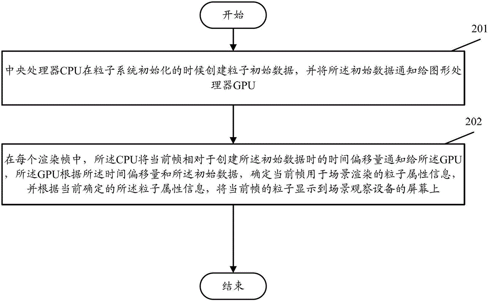
[0022] In order to make the purpose, technical solution and advantages of the present invention clearer, the present invention will be further described in detail below in conjunction with the accompanying drawings and specific embodiments.

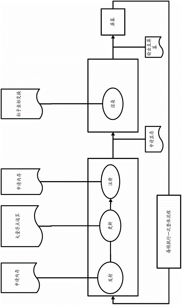
[0023] Considering that when there is a need for large-scale particle rendering, the update of particles requires large-scale floating-point unit operations. Compared with the CPU, the GPU has a large number of floating-point calculation units and is more suitable for this work. Based on this, the core idea of ​​the present invention is: the calculation operation of the particle attributes of each frame is transferred to the GPU for realization, and the particle attributes of each frame are determined by the GPU according to the initial particle data created by the CPU and the current time offset parameters of each frame In this way, the CPU can be liberated from the complicated floating-point calculations, and at the same time, the freque...


PUM


Abstract

The invention provides a method for rendering a computer simulation scene. The method comprises the steps that: a central processing unit (CPU) builds a particle initial data and informs a graphics processing unit (GPU) of the initial data when a particle system is initialized; in each rendering frame, the CPU informs the GPU of the time offset amount of the current frame relative to the initial data generated during the building, the GPU determines the particle attribute information of the current frame for scene rendering according to the time offset amount and the initial data, and displays the particles of the current frame on a screen of a scene observation device according to the particle attribute information currently confirmed. The rendering effect is improved after the method is adopted.

Description

technical field [0001] The invention relates to computer application technology, in particular to a computer simulation scene rendering method in computer graphics processing. Background technique [0002] At present, in order to enhance the reality of the scene and the degree of immersion to the user, the computer simulation system introduces particle systems into its rendering system to simulate various natural phenomena. Particle system is a technology in 3D computer graphics that simulates some scenes with blurred phenomena in reality. For these blurring phenomena, it is difficult to achieve realistic visual effects using other traditional rendering techniques. Phenomena that are often simulated using particle systems are fire, explosions, smoke, water flow, sparks, fallen leaves, clouds, fog, snow, dust, meteor trails, or abstract visual effects such as glowing trails. The emergence of particle system technology has also brought a qualitative leap in the improvement o...

Claims


Application Information

Patent Timeline
IPC IPC(8): G06T1/00
Inventor 于静波
Owner BEIJING PIXEL SOFTWARE TECH
Why Eureka
Try Eureka