Hexagonal resonant cavity substrate integrated waveguide filter

A substrate-integrated waveguide and resonant cavity technology, applied in waveguide devices, electrical components, circuits, etc., can solve problems such as low Q value and inflexible structural design, and achieve high no-load quality factor, good flexibility, highly selective effect

Inactive Publication Date: 2014-08-06
UNIV OF ELECTRONICS SCI & TECH OF CHINA
View PDF4 Cites 0 Cited by
  • Summary
  • Abstract
  • Description
  • Claims
  • Application Information

AI Technical Summary

Problems solved by technology

In comparison, the rectangular resonant cavity has a flexible structure and is easy to design, but its Q value is relatively low. The circular resonant cavity has a high Q value, but its structural design is not flexible enough.

Method used


Image

  • Hexagonal resonant cavity substrate integrated waveguide filter
  • Hexagonal resonant cavity substrate integrated waveguide filter
  • Hexagonal resonant cavity substrate integrated waveguide filter

Examples


Embodiment 1

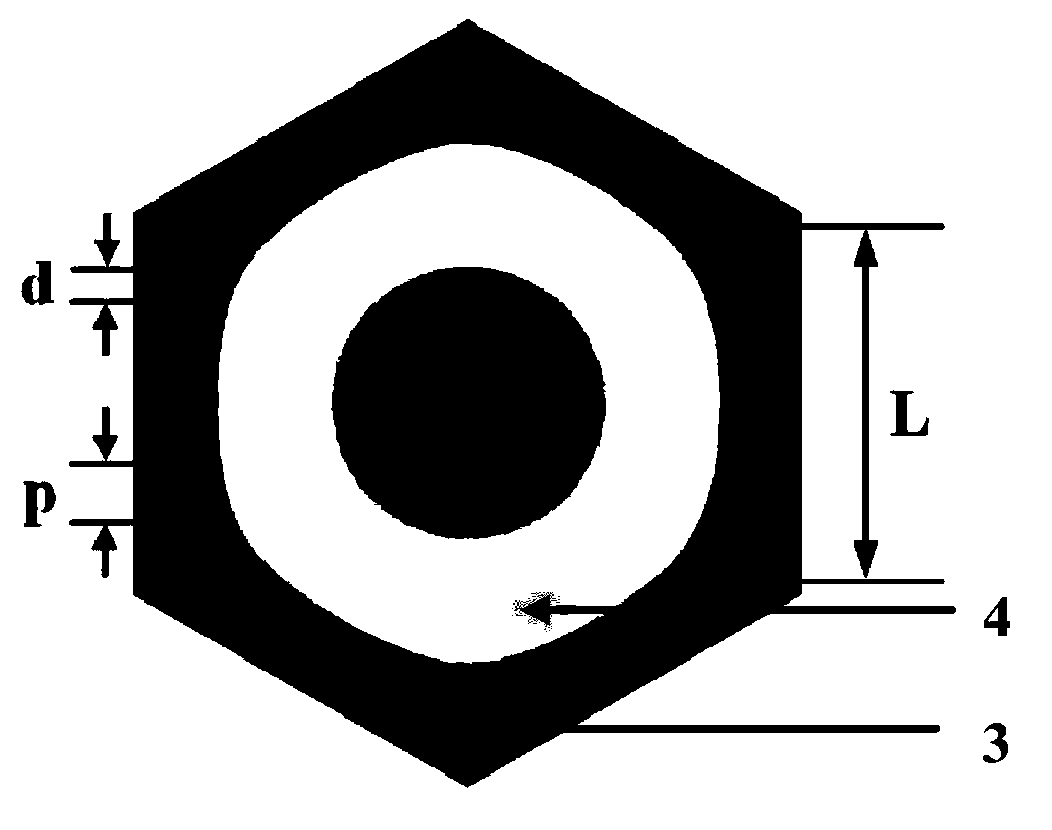
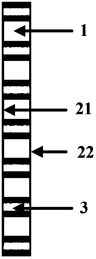
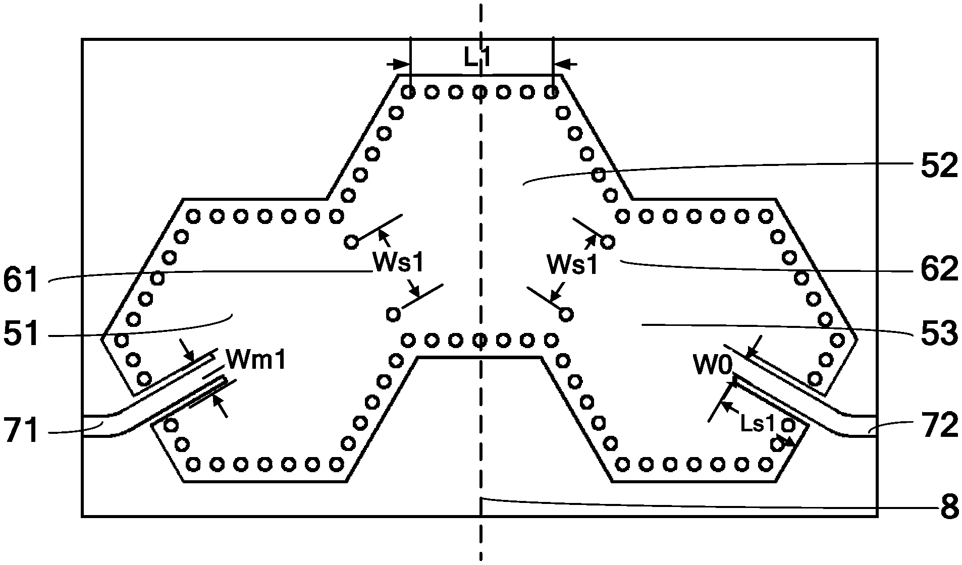
[0015] Embodiment 1: as Figure 1a , Figure 1b and figure 2 As shown, the hexagonal resonant cavity substrate integrated waveguide filter, the filter includes a dielectric substrate 1 and the upper surface metal copper 21 and the lower surface metal copper 22 respectively located on the upper surface and the lower surface of the dielectric substrate 1; The through holes of the metallization 3 penetrate the dielectric substrate 1 and conduction with the metal copper 21 on the upper surface and the metal copper 22 on the lower surface, and the array of the metallization 3 forms a regular hexagonal first hexagonal resonant cavity connected in sequence 51. The second hexagonal resonant cavity 52 and the third hexagonal resonant cavity 53; Axis 8 is mirror symmetrical but not adjacent; the upper right side of the first hexagonal resonant cavity 51 coincides with the lower left side of the second hexagonal resonant cavity 52 and is provided with a first inductive coupling window ...

Embodiment 2

[0018] Embodiment 2: as Figure 1a , Figure 1b and image 3 As shown, the hexagonal resonant cavity substrate integrated waveguide filter, the filter includes a dielectric substrate 1 and the upper surface metal copper 21 and the lower surface metal copper 22 respectively located on the upper surface and the lower surface of the dielectric substrate 1; The through holes of the metallization 3 penetrate the dielectric substrate 1 and conduction with the metal copper 21 on the upper surface and the metal copper 22 on the lower surface, and the array of the metallization 3 forms a regular hexagonal first hexagonal resonant cavity connected in sequence 51, the second hexagonal resonant cavity 52 and the third hexagonal resonant cavity 53; the first hexagonal resonant cavity 51, the second hexagonal resonant cavity 52 and the third hexagonal resonant cavity 53 with The apex mode is evenly arranged; the upper right side of the first hexagonal resonant cavity 51 coincides with the ...


PUM


Abstract

The invention relates to a hexagonal resonant cavity substrate integrated waveguide filter, which includes a dielectric substrate and metal copper on the upper surface and metallic copper on the lower surface respectively located on the upper surface and the lower surface of the dielectric substrate; the metallized through hole array is formed after The first hexagonal resonant cavity, the second hexagonal resonant cavity and the third hexagonal resonant cavity connected in sequence; the first hexagonal resonant cavity and the third hexagonal resonant cavity The central axis of the second hexagonal resonant cavity is mirror-symmetrical but not adjacent; the upper right side of the first hexagonal resonant cavity coincides with the lower left side of the second hexagonal resonant cavity and is provided with a first inductive coupling window; The lower right side of the second hexagonal resonant cavity coincides with the upper left side of the third hexagonal resonant cavity and is provided with a second inductive coupling window; the lower left side of the first hexagonal resonant cavity is provided with a coplanar The waveguide input end is provided with a coplanar waveguide output end on the lower right side of the third hexagonal resonant cavity.

Description

technical field [0001] The invention belongs to the field of microwave and millimeter wave filters, in particular to a substrate integrated waveguide filter. Background technique [0002] The filter is the basic unit circuit in the microwave circuit, and its performance directly affects the performance of the entire system. Traditional filters are generally divided into planar microstrip / stripline structure filters and metal waveguide structure filters. Although the planar microstrip / stripline structure filter is easy to integrate, it occupies a large area, has a large loss, and has a low Q value. Although the metal waveguide structure filter has the characteristics of small insertion loss, high quality factor, and good selectivity, it is bulky, troublesome in processing and debugging, and is not conducive to integration with active circuit substrates. [0003] The filter based on the substrate integrated waveguide technology not only retains the characteristics of high Q ...

Claims


Application Information

Patent Timeline
Patent Type & Authority Patents(China)
IPC IPC(8): H01P1/208
Inventor 徐自强徐美娟夏红廖家轩尉旭波
Owner UNIV OF ELECTRONICS SCI & TECH OF CHINA
Why Eureka
Try Eureka