Transfer bar

一种传动杆、移动杆的技术,应用在传动杆领域,能够解决传动杆高速驱动化障碍、无法对抗弯曲力矩、负载刚性低等问题,达到实现轻量化、润滑简单、平衡性良好的效果

Active Publication Date: 2012-10-10
KOMATSU LTD +2
View PDF11 Cites 2 Cited by
  • Summary
  • Abstract
  • Description
  • Claims
  • Application Information

AI Technical Summary

Problems solved by technology

[0010] However, the connecting structures disclosed in the above-mentioned Patent Documents 1 and 2 are structures in which the plate-shaped engaging member and the clamp provided on the residual rod swing up and down, and are engaged with the engaged part on the side of the moving rod from the vertical direction. Therefore, although the load in the vertical direction due to the own weight of the transmission rod itself or the acceleration when moving up and down can be sufficiently tolerated, there is a problem that the rigidity to the load in the horizontal direction is low.
Therefore, when the transmission rod is driven at a higher speed in order to improve the productivity of the press machine, not only a vertical load but also a horizontal load acts as a large bending moment on the joints of the rods. , thus creating the problem of not being able to resist this bending moment
In addition, when the device is enlarged in order to be able to resist the load from the horizontal direction, the weight increases, which becomes an obstacle to high-speed drive of the transmission rod.

Method used


Image

  • Transfer bar
  • Transfer bar
  • Transfer bar

Examples


no. 1 approach 〕

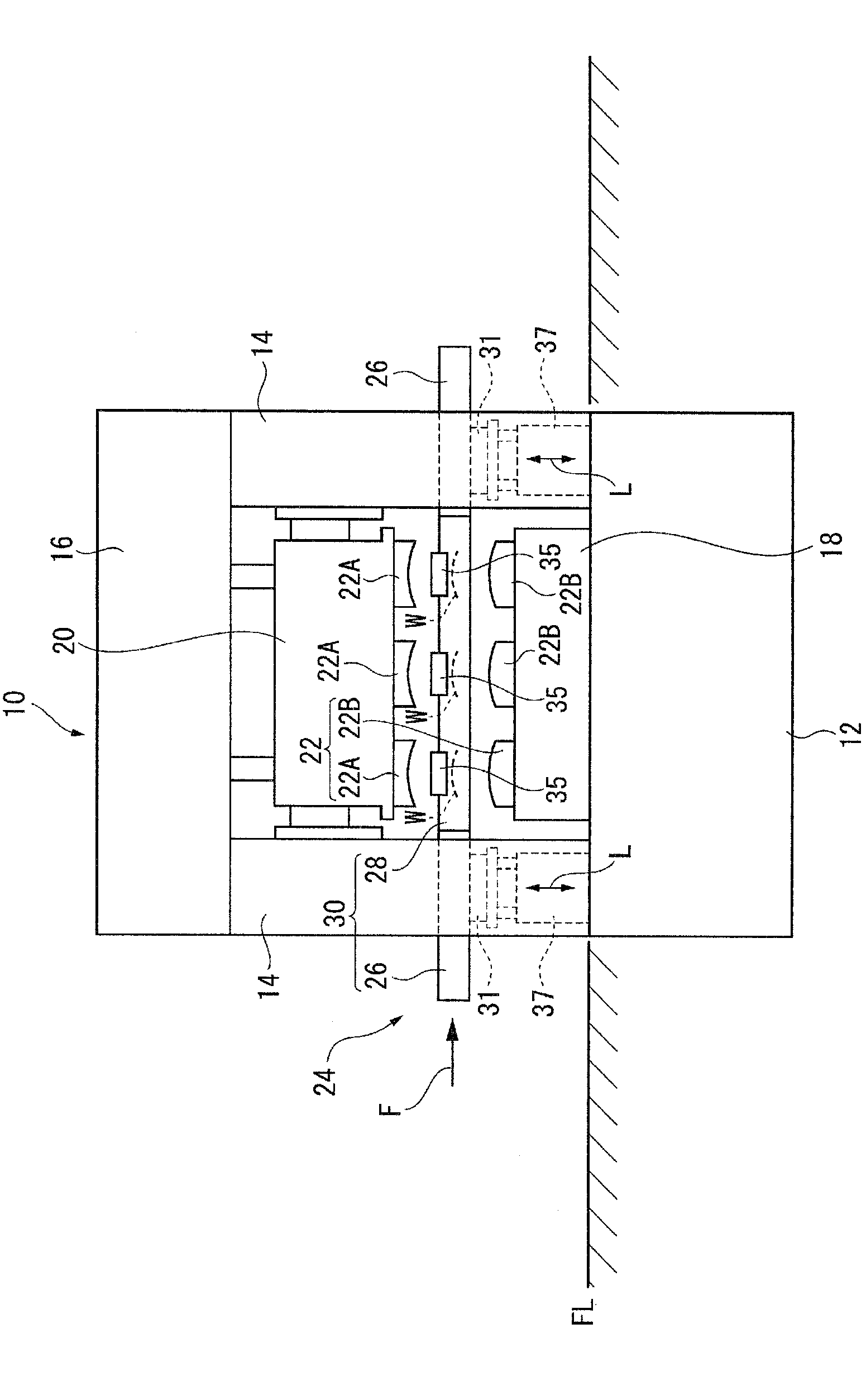
[0037] Hereinafter, the first embodiment of the present invention will be described in detail using the drawings. figure 1 A continuous automatic press machine 10 as a press machine is shown in a front view, and a machine tool 12 having a rectangular shape in plan view is buried under the floor FL. Columnar columns 14 are erected at four corners of the machine tool 12 in plan view. A beam 16 is supported on these four columns. A slider 20 is suspended from the beam 16 , and the slider 20 can be driven up and down by an appropriate drive mechanism inside the beam 16 . The press body of the continuous automatic press machine 10 is thus formed.

[0038] A movable workbench 18 is provided on the machine tool 12 . The movable table 18 can be smoothly carried out from the press main body to the outside or carried in from the outside along an appropriate guide mechanism such as rails. A lower mold 22B among the molds 22 for processing the workpiece W is mounted on the upper surfa...

no. 2 approach 〕

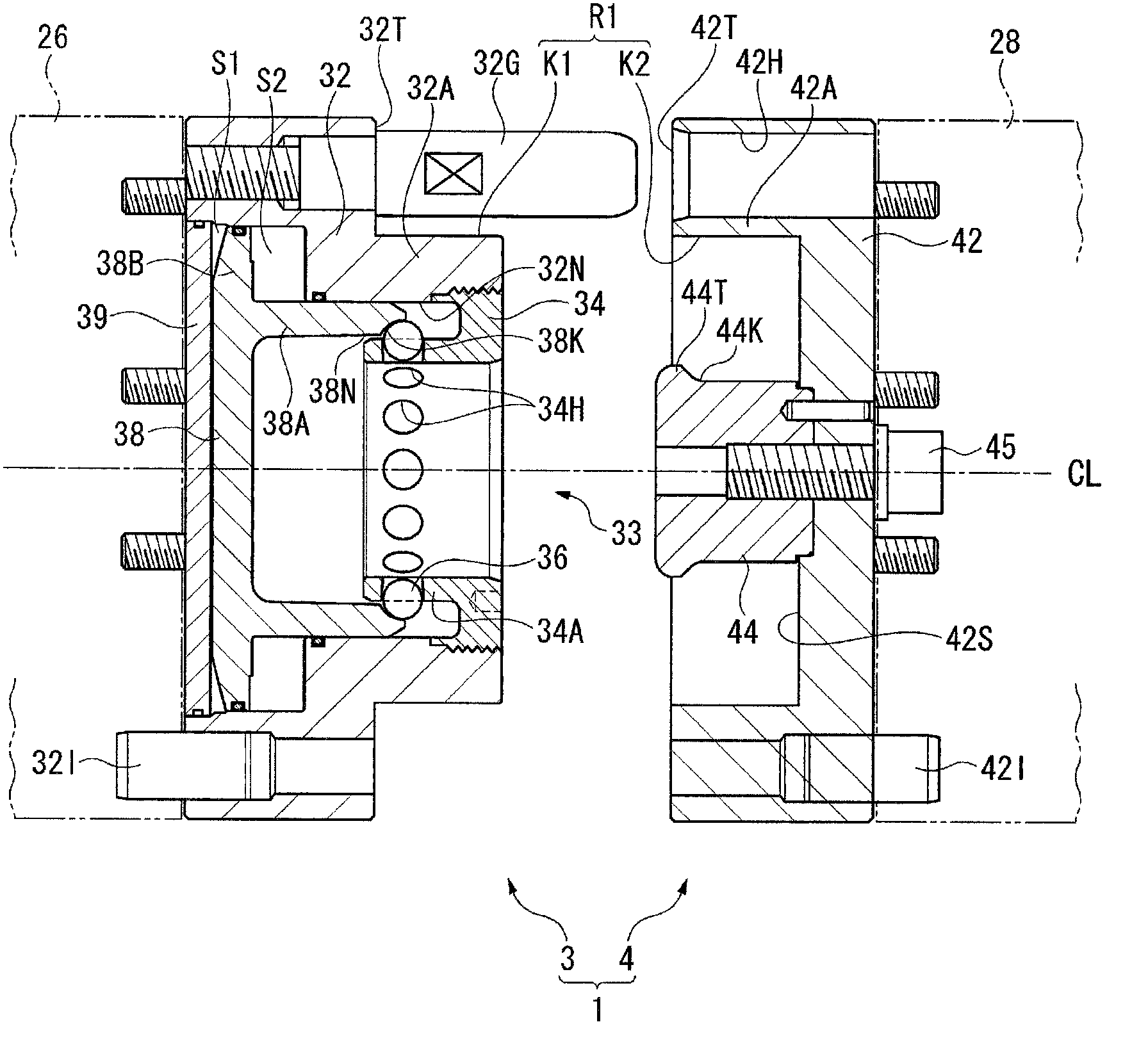
[0065] Image 6 The second embodiment of the present invention is shown. In the first embodiment, the male fitting portion K1 and the female fitting portion K2 of the first connection portion R1 are formed by planes parallel to the central axis CL, but in this embodiment, each is formed by a truncated conical cone. face formed. That is, the male fitting part K1 is formed as a frustum-shaped outer peripheral tapered surface that decreases in diameter toward the tip in the fitting direction (same as the connecting direction), and the female fitting part K2 is formed as a tapered surface on the outer peripheral side that decreases in diameter toward the fitting direction. The tapered surface on the inner peripheral side of the truncated conical shape that expands at the front end.

[0066] According to such a second embodiment, there is an effect that the respective fitting portions K1 , K2 can be reliably brought into ground contact with each other over the entire circumferenc...

no. 3 approach 〕

[0068] Figure 7 The third embodiment of the present invention is shown. In the first embodiment, the ball 36 is used as the moving member of the present invention, but in this embodiment, the cylindrical roller 51 having a predetermined length is used. Therefore, on the holding member 34, instead of the inner cylindrical portion 34A described in the first embodiment, a square inner square tube portion 34C is provided, and each piece portion forming the inner square tube portion 34C is provided with a The through-holes 34H opened in a square shape each accommodate a roller 51 in each through-hole 34H.

[0069] On the other hand, in the plunger 38 , the front end side of the intermediate cylindrical portion 38A becomes the intermediate square cylindrical portion 38C. Furthermore, in the remaining side outer profile member 32, the inner peripheral shape of the outer cylindrical portion 32A is defined by the circular opening portion contacted by the outer peripheral surface of ...


PUM


Abstract

A connection device (1) for connecting a remaining bar (26) and a movement bar (28) of a transfer bar (1) is configured of a remaining clamp (3) and a movement clamp (4). A male fitting section (K1) and a female fitting section (K2) which fit to each other in the connection direction are provided to the clamps (3, 4) so as to serve as a first connection section (R1). A male engagement section (44) and a female engagement section (33) are contained within the clamps (3, 4) so as to serve as a second connection section (R2). The female engagement section (33) of the second connection section comprises spheres (36) serving as movement members which move in the direction perpendicular to the connection direction. The female engagement section (33) is engaged with and disengaged from the male engagement section (44) by the movement of the spheres (36).

Description

technical field [0001] The present invention relates to a transmission rod, in particular to a connection structure of a transmission rod provided on a work conveying device of a press machine. Background technique [0002] The continuous automatic press machine is a press machine of the type provided with a plurality of processing stations in the main body of the press machine, and the continuous automatic press machine is provided with a workpiece transfer device that sequentially transfers workpieces between the respective processing stations. The workpiece conveying device has a pair of transmission rods arranged parallel to the workpiece conveying direction, and each transmission rod is equipped with a detachable workpiece holder, which can be mounted corresponding to the mold provided on each processing table. Hold the workpiece or leave the workpiece. [0003] The molds described above need to be replaced according to the type of workpiece (type of product). The low...

Claims


Application Information

Patent Timeline
Patent Type & Authority Applications(China)
IPC IPC(8): B21D43/05
CPCB21D43/057B21D43/055
Inventor 西田宪二守安隆史明石秀利小林智也
Owner KOMATSU LTD
Why Eureka
Try Eureka