Iron rod type golf rod head

A technology for golf clubs and club heads, which is applied to golf balls, golf clubs, rackets, etc., and can solve the problems of larger flight distance difference, larger rebound difference, unstable flight distance, etc., and achieves less deviation in flight distance , Improve the effect of rebound

Active Publication Date: 2012-10-17
DAIWA SEIKO CORPORATION
View PDF7 Cites 0 Cited by
  • Summary
  • Abstract
  • Description
  • Claims
  • Application Information

AI Technical Summary

Problems solved by technology

In particular, when the face of an iron golf club head is viewed in the top-sole direction, the toe side is long and the heel side is short. Therefore, as mentioned above, when ribs of equal width and height are formed on the back of the face , there is a tendency to suppress the deflection of the heel side of the club face, thereby, the rebound difference between the shot at the center position and the shot on the heel side becomes large, and the difference in flight distance becomes large when the hitting point is shifted (flight Unstable distance)
[0008] Furthermore, in the club head provided with ribs as disclosed in the above-mentioned Patent Document 2, when the impact point is shifted in the toe-heel direction, the impact point at the position where the rib is formed and the position at other positions There is a rebound difference between the hit points, and the flight distance difference caused by the offset of the hit point becomes larger, and the flight distance is unstable

Method used


Image

  • Iron rod type golf rod head
  • Iron rod type golf rod head
  • Iron rod type golf rod head

Examples


Embodiment Construction

[0026] Hereinafter, embodiments of an iron-type golf club head according to the present invention will be described with reference to the drawings.

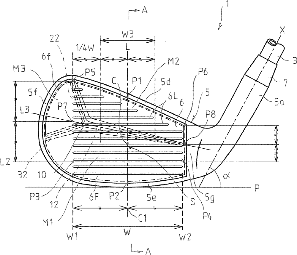
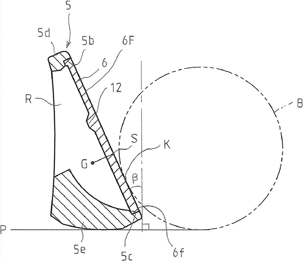
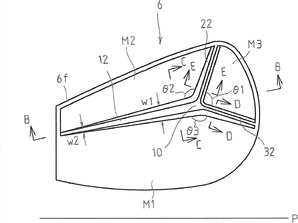
[0027] Figure 1 to Figure 3 is a diagram showing an embodiment of the present invention, figure 1 It is a front view of an iron type golf club head, figure 2 is along figure 1 A sectional view of line A-A, and, image 3 It is the figure which looked at the club surface from the back side.

[0028] The golf club head according to this embodiment includes a club head body 5 and a club surface (piece) 6 formed separately from the club head body 5, and is configured by fixing and installing the club head body 5 on the front end of the shaft 3. golf clubs1. When the club head body 5 is fixedly attached to the shaft 3 and the golf club 1 is assembled with respect to the reference horizontal plane P, a predetermined lie angle α is set between the axis X of the shaft 3 and the reference horizontal plane P.

[0029] A hosel 5a is ...


PUM


Abstract

The present invention provides an iron rod type golf rod head, which can increase resilience, and simultaneously realize light weight and high strength of the surface portion of the rod. Even if golf ball knocking point offset appears in a toe and heel direction, the flying distance deviation is small. Compared with the central position (C) of an effective golf ball knocking point area (W), the surface portion (6) of the iron rod type golf rod head is provided with a maximum thick wall portion (10) at the toe side, and a rib (12) extending from the maximum thick wall portion (10) to heel side is formed on the back side of the surface portion of the rod (6). And the cross section of the rib (12) decreases from the maximum thick wall portion (10) to heel side.

Description

technical field [0001] The present invention relates to an iron-type golf club head. Background technique [0002] Conventionally, as an iron-type golf club head, there is known a club head in which the back side of the club face that hits the ball is formed into a cavity structure. With this head structure, the weight is distributed around the face and the weight on the sole can be made larger, so the center of gravity can be lowered, the moment of inertia can be increased, and the hitting direction can be stabilized. [0003] The club head with the above-mentioned cavity structure can improve repulsion and increase the moment of inertia by making the club face (face part) thinner and thicker, but if the club face is too thin and thick, the strength will decrease, and the club face The center tends to bend, resulting in decreased directionality and poor hitting feeling. [0004] Then, as disclosed in Patent Document 1, it is known to form ribs on the bottom surface of the...

Claims


Application Information

Patent Timeline
IPC IPC(8): A63B53/04A63B102/32
Inventor 饭嶋淳
Owner DAIWA SEIKO CORPORATION
Why Eureka
Try Eureka