Vertical mill inlet shared induction device

A vertical rolling mill and entrance technology, applied in the direction of guiding/positioning/aligning devices, etc., can solve the problems of shortening the service cycle of the guiding device, the lack of commonality of the guiding device, and prolonging the replacement time, so as to reduce the reserve of spare parts and Expenses, avoid scratch defects, reduce the effect of production costs

Active Publication Date: 2014-03-12
ANGANG STEEL CO LTD
View PDF6 Cites 4 Cited by
  • Summary
  • Abstract
  • Description
  • Claims
  • Application Information

AI Technical Summary

Problems solved by technology

[0003] 1. The friction between the rolled piece and the guide device is sliding friction, and the sliding friction between the hot rolled piece and the cold guide can easily cause scratches on the surface of the rolled piece, directly affecting the surface of the finished product quality
[0004] 2. The guide device has no commonality
The guide cavity of the roll pass cannot be adjusted or is difficult to adjust. When changing the rolling variety or the roll system, the guide and guard device must be replaced together, which not only increases the spare parts reserve and capital occupation of the guide and guard device; but also shortens the guide device. The service life of the equipment increases the production cost; at the same time, the replacement time is prolonged, which seriously affects the operation rate of the equipment and the production capacity of the rolling line
[0005] In order to eliminate the above defects, experts from various fields have been organized for many times to discuss and tackle key problems. However, due to the limitation of the space position (the height of this area is only 1130 mm, and the width is only 610 mm), the strength of the components cannot be guaranteed, and it is difficult to correctly place the rolled parts. introduced into the rolling mill, so this problem has not been effectively solved

Method used


Image

  • Vertical mill inlet shared induction device
  • Vertical mill inlet shared induction device
  • Vertical mill inlet shared induction device

Examples


Embodiment Construction

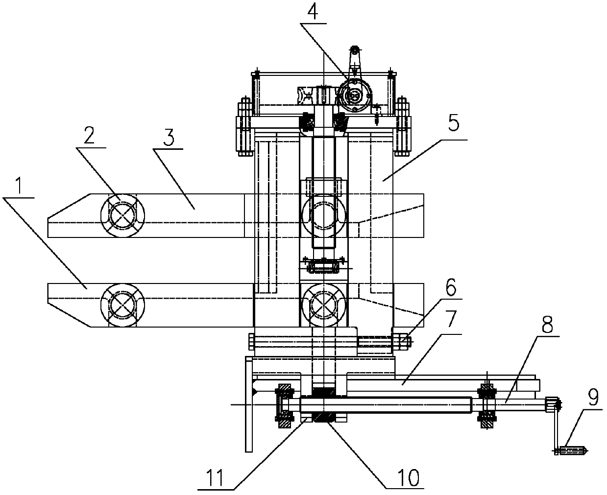
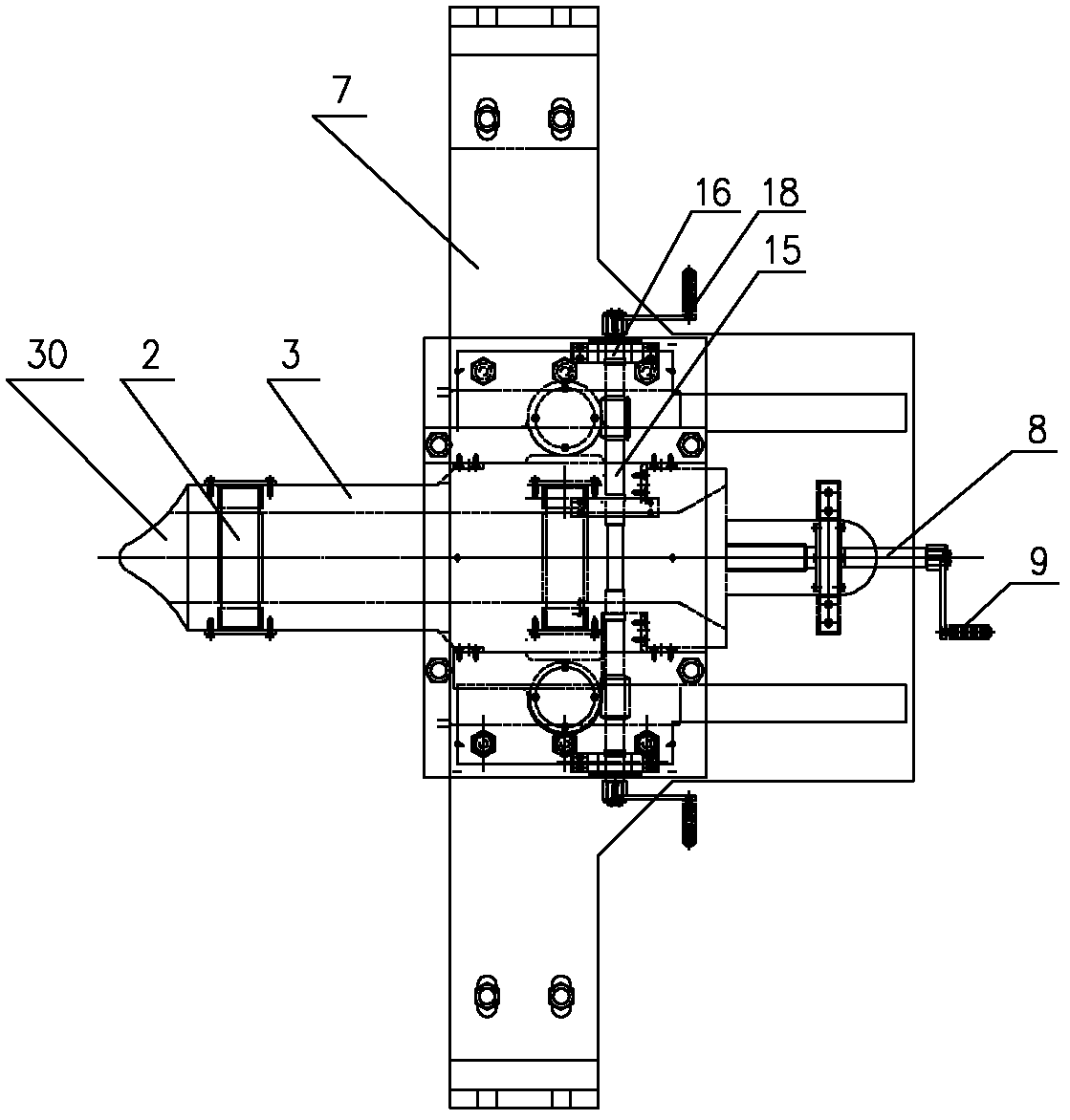
[0028] As can be seen from the accompanying drawings, the vertical rolling mill entrance shared induction device of the present invention is mainly composed of a lower support arm 1, a guide roller 2, an upper support arm 3, a guide roller opening adjustment mechanism 4, a guide body 5, a fixed bracket 7, a guide Guard body horizontal moving mechanism 21 and corresponding connector are formed.

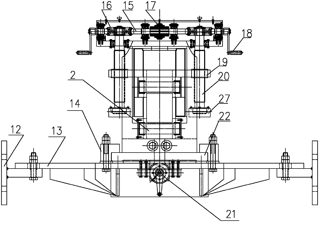
[0029] The fixed bracket 7 as a bracket for the horizontal movement of the guide body 5 is in the shape of a "T" as a whole, and is assembled by a frame body 13 and an ear plate 12 . A limit baffle 23 is fixed on the inner side of the frame body 13, and a chute 24 is processed in the middle of the upper surface of the frame body 13, and the limit baffle 23 and the chute 24 can carry out horizontal and vertical direction adjustment to the guide body 5 respectively. limit. Simultaneously, on the upper surface of the frame body 13, there are also two inverted "L" shaped pressure plates 1...


PUM


Abstract

The invention provides a vertical mill inlet shared induction device, which consists of a fixing bracket, a guide body, an upper supporting arm, a lower supporting arm, a guide roller, a guide roller opening adjusting mechanism and a guide body horizontal movement mechanism, wherein the billet moves in a space formed by the upper and lower supporting arms and a side baffle, is guided by the guide roller and the side baffle and is correctly engaged with a rolling mill; when the milling specification is changed, an adjusting handle is rotated, the upper supporting arm drives the upper guide roller to lift to meet the novel specification requirement; the supporting arm stretches into two rollers on an inner frame, the guide plate body moves backwards in the process of replacing the rollers, and the supporting arms and the guide rollers retract the rollers and the arch of the inner frame; and therefore, the guide device is not required to be replaced in the process of replacing the rollers, the roller replacing time can be obviously shortened, the operate rate of the rolling mill is improved, the service life of the guide device is greatly prolonged, the storage and consumption of spare parts are reduced, and the production cost is reduced; and meanwhile, the scratch defect on the surface of a rolled piece can be overcome, and the quality of the finished rolled product is improved.

Description

technical field [0001] The invention belongs to the field of steel rolling machinery and equipment, and in particular relates to a common induction device for fixing the entrance of a vertical rolling mill entrance of a square and round steel finished product of a continuous rolling mill in a rolling line. Background technique [0002] The steel rolling line of the fixed rolling line continuous rolling mill is fixed. During the rolling process, it mainly relies on the left and right movement of the horizontal rolling mill frame and the up and down movement of the vertical rolling mill frame to make the passes of each frame of the same variety Align the rolling line to realize rolling of different varieties. When the continuous rolling mill produces square and round steel, the shape of the finished front stand is: the square steel is rectangular, and the round steel is elliptical. And the shape of the finished product and the front stand is all square for the continuous...

Claims


Application Information

Patent Timeline
Patent Type & Authority Patents(China)
IPC IPC(8): B21B39/16
Inventor 曹维华马成郑显亮臧绍双王荣李阳
Owner ANGANG STEEL CO LTD
Why Eureka
Try Eureka