

Chip-free cutting apparatus used for plastic section bar
A technology of plastic profiles and cutting devices, which is applied in metal processing and other directions, can solve problems such as increased production costs, hidden dangers of production and maintenance, and easy chipping of cutters, so as to improve safety performance, prevent cutters from chipping, and buffer cutting resistance Effect
- Summary
- Abstract
- Description
- Claims
- Application Information
AI Technical Summary
Problems solved by technology
Method used
Image

Examples
Embodiment Construction
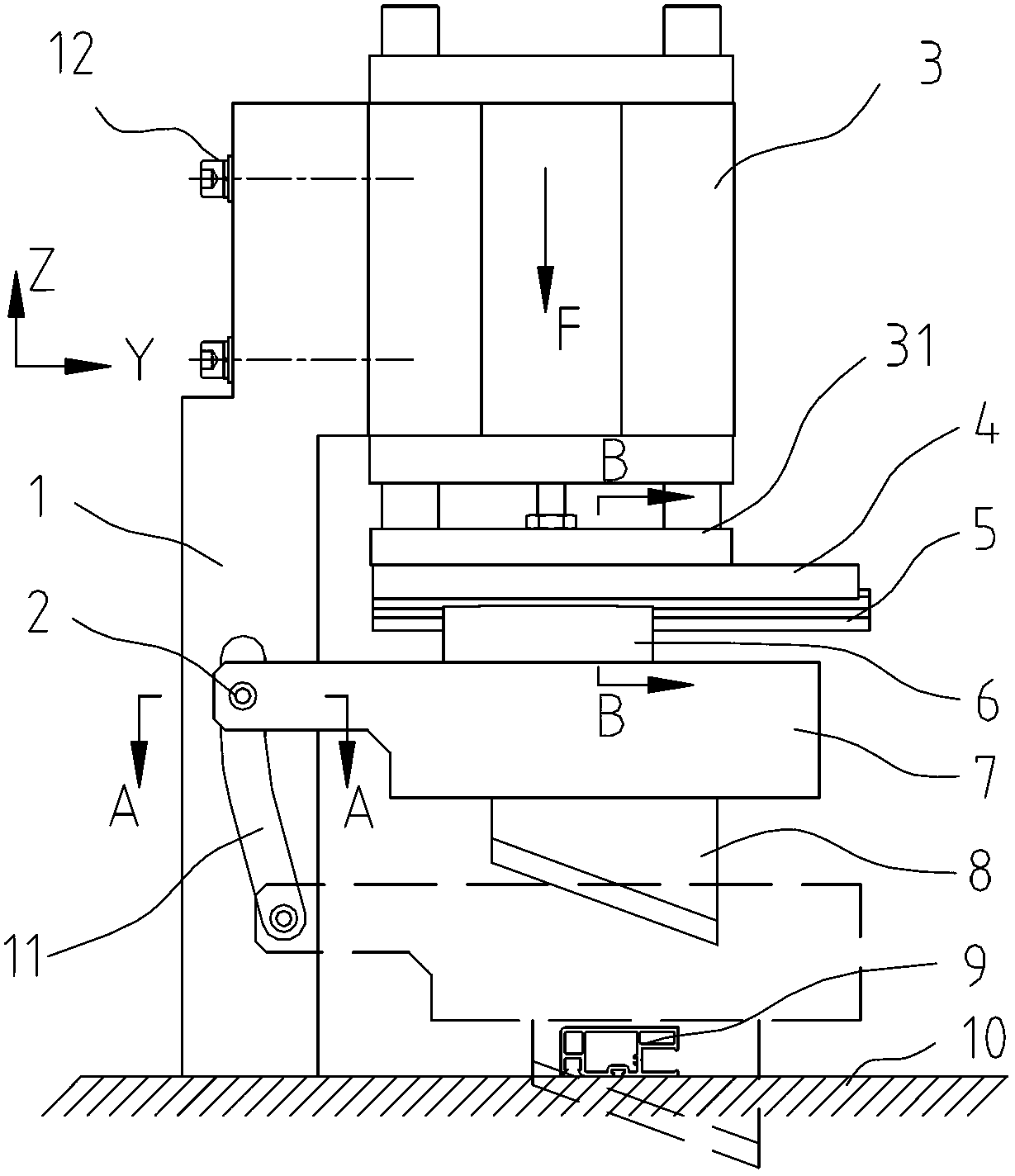
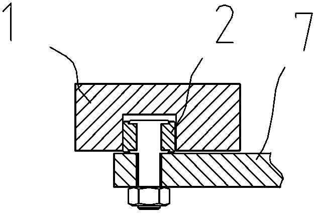
[0012] Such as figure 1 As shown, the support 1 is fixed on one side of the workbench 10, the driving cylinder 3 is fixed on the upper end of the support 1 by bolts 12, and the side of the support 1 is provided with a guide groove 11 inclined or curved from top to bottom to the cutting knife 8 side. One end of the frame 1 is fixed with a ball bearing follower 2 cooperating with the guide groove 11 on the bracket 1, see figure 2 , Cutter 8 is fixed on knife rest 7 lower ends.
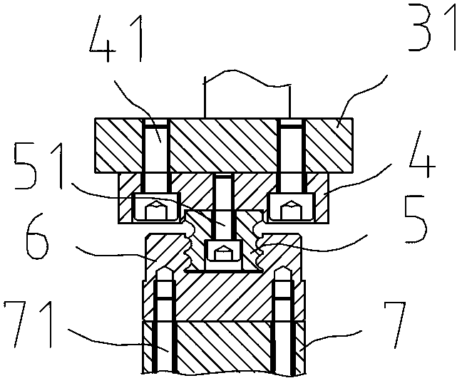
[0013] The knife rest 7 is connected with the cylinder head 31 of the driving cylinder 3 through a horizontal sliding device, and its structure is as follows: image 3 As shown, the guide rail frame 4 is fixed on the lower end of the cylinder head 31 of the drive cylinder by bolts 41, the linear guide rail 5 is fixed on the lower end of the guide rail frame 4 by bolts 51 along the horizontal direction of the plane where the cutting edge is located, and the slide block 6 is fixed by bolts 71 7. On the ...
PUM
 Abstract
Description
Claims
Application Information