Automatic circulation screen filter device for blow-molding melt

An automatic circulation and net filtration technology, which is applied in the field of filtration devices of plastic machinery, can solve the problems of increased processing difficulty, waste of filter nets, and increased costs, and achieve the effects of improving production efficiency, saving time, and reducing defective products

Active Publication Date: 2012-10-17
ZHEJIANG UNIV
View PDF9 Cites 12 Cited by
  • Summary
  • Abstract
  • Description
  • Claims
  • Application Information

AI Technical Summary

Problems solved by technology

[0004] Problem 1: The single channel plate type or cylindrical filter device cannot realize continuous screen change when replacing the filter screen, resulting in changes in pressure and melt temperature when changing the screen, which affects product quality
There is no automatic cleaning filter device, so it needs to be taken out and cleaned after the filter is clogged, which is inconvenient to operate
[0005] Problem 2: The flow channel of the double-channel plate or cylindrical filter device is long, and it is easy to remain. When the production volume is small, the flow of the two flow channels is prone to unevenness, causing one flow channel to be blocked after a long working time
The internal structure is complex, the processing difficulty is increased, the cost is increased, and there is no automatic cleaning
[0006] Problem 3: The mesh belt filter device can realize continuous and uninterrupted screen replacement, but it cannot automatically clean the filter screen, which is a serious waste of the filter screen, and the filter screen belt of the filter device needs to be replaced with a new one after use. This replacement process requires shutdown operations, which affects the production efficiency of the product

Method used


Image

  • Automatic circulation screen filter device for blow-molding melt
  • Automatic circulation screen filter device for blow-molding melt
  • Automatic circulation screen filter device for blow-molding melt

Examples


Embodiment Construction

[0020] The present invention will be further described below in conjunction with the accompanying drawings and embodiments.

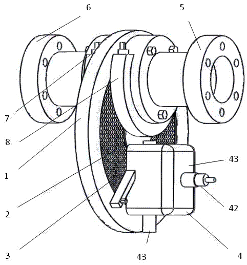
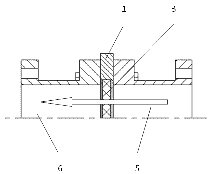
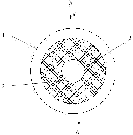
[0021] like figure 1 , figure 2 , image 3 Shown, the present invention comprises outer filter disc 1, inner filter disc 2, filter screen 3, enters melt chamber 5, goes out melt chamber 6, two cooling water pipes 7,8 and cleaning device 4; Outer filter disc 1 and the inner filter disc 2 are equipped with a filter screen 3, the melt inlet cavity 5 and the melt outlet cavity 6 are arranged on both sides of the filter mesh ring, the cleaning device 4 is arranged on one side of the filter mesh ring, two cooling water pipes 7 and 8 are respectively installed on the flange cylindrical surface close to the filter screen 3 in the melt chamber 5 and the melt chamber 6. In the figure, the two cooling water pipes surround the lower half of the flange cylindrical surface and exceed the flange cylindrical surface 1 / 2 circle, the cooling water solidifies the melt...


PUM


Abstract

The invention discloses an automatic circulation screen filter device for a blow-molding melt. The automatic circulation screen filter device comprises an external circular filtering plate, an internal circular filtering plate, a filter screen, a melt-supplying cavity, a melt-discharging cavity, two cooling water pipes and a cleaning device, wherein the filter screen is disposed between the external circular filtering plate and the internal circular filtering plate; the melt-supplying cavity and the melt-discharging cavity are disposed at two sides of the filter screen; the cleaning device is disposed at one side of a filter screen ring; and the cooling water pipes are respectively disposed on flanged cylindrical surfaces, adjacent to the filter screen, of the melt-supplying cavity and the melt-discharging cavity. The circular filter screen is used in the automatic circulation screen filter for the blow-molding melt and driven to move in a circular filtering plate tank by the rotation of a cleaning felt shaft of the cleaning device so as to complete the filter screen replacement. The replacement of the filter screen needs no stop and is continuous, and therefore, the flow velocity and pressure of charged materials and discharged materials change slightly, and the unqualified products are reduced as well as the production efficiency is improved. In addition, the filter screen can be recycled after being cleaned automatically, thereby saving materials and time.

Description

technical field [0001] The invention relates to a filtering device for plastic machinery, in particular to an automatic circulating net filtering device for blow molding melt. Background technique [0002] In the process of using plastic as raw material to produce various finished products, no matter whether the raw material is new material or recycled material, there must be more or less various impurities mixed in it. In addition, during the plastic extrusion process, the plastic melt is plasticized and heated for a long time, and the melt will produce residues. Impurities and residues in these raw materials, once entering the extrusion die, will cause flow channel blockage or product defects, affect the quality of finished products and the continuity and stability of production, and even make production impossible. In order to eliminate these granular impurities, make the pure melt enter the extrusion die smoothly, and obtain high-quality products, it is necessary to pla...

Claims


Application Information

Patent Timeline
Patent Type & Authority Applications(China)
IPC IPC(8): B29C47/68B29C49/42B29C49/04
Inventor 张树有王晓丽
Owner ZHEJIANG UNIV
Why Eureka
Try Eureka