
Patsnap Eureka
For R&D, Patsnap Eureka makes reading and utilizing patents & technical documents easy.
Patsnap Eureka AIR
Designed for self-driven R&D workflows. Generate viable solutions, solve complex R&D challenges, empower your innovation with AI.

Patsnap Eureka Materials
Designed for material experts only. Revolutionize your material R&D, from search, analyze, to developing new materials.

TechResearch
Generate reliable direction feasibility study reports for your R&D in just a few steps.

TechSeek
Discover and master advanced knowledge NOW. Basics, ideas, possibilities, all at once.

TechMind
As an expert in R&D Theories, TechMind can generates customized viable solutions instantly.

TechRisk
Analyze your overall solution with one click, know your potential R&D risks in advance.

TechMonitor
Get weekly tech updates, stay abreast of the latest tech innovations and key insights.
Jacket unit, jacket tank and manufacture method of jacket tank
A manufacturing method and jacket technology, applied to tank cars, transport passenger cars, railway car body parts, etc., can solve the problems of reducing the thickness of the tank body plate 4, the high material cost of the jacket tank 1, and the lack of reinforcement of the tank body 2, etc.
- Summary
- Abstract
- Description
- Claims
- Application Information
AI Technical Summary
Problems solved by technology
Method used
Image

Examples
Embodiment Construction
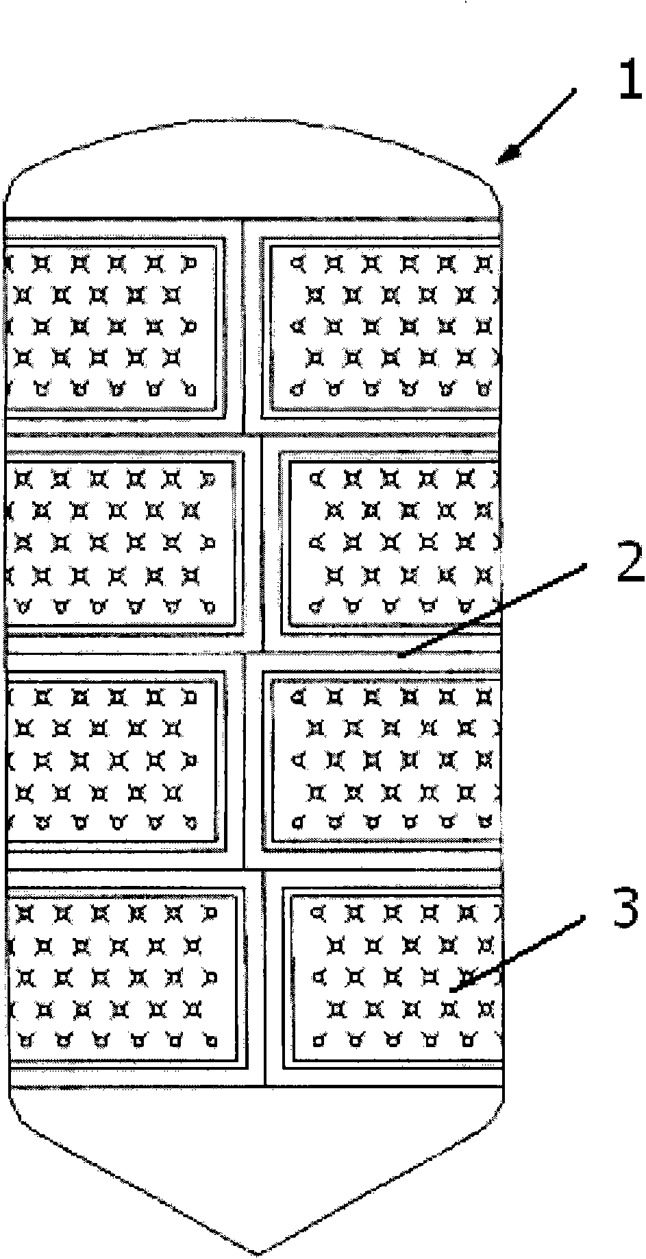
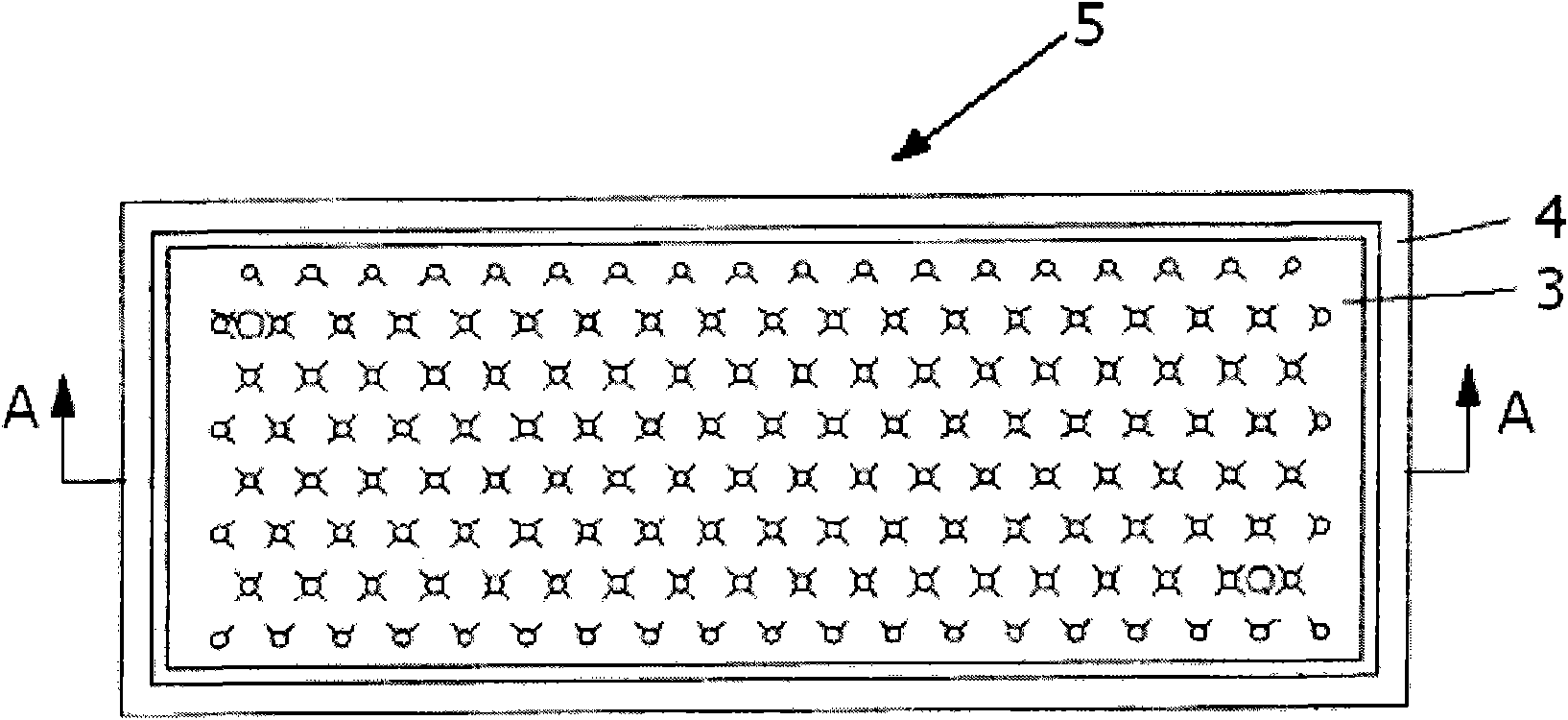
[0025] Figure 4 The overall structure of the honeycomb jacketed tank 11 according to one embodiment of the present invention is schematically shown. Figure 5a with 5b is shown for forming Figure 4 The specific structure of the individual jacketed unit 15 of the jacketed tank 11 is shown.
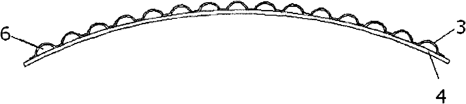
[0026] Such as Figure 5a with 5b As shown, the jacket unit 15 consists of a thinner jacket plate 13 and a thicker tank plate 14 . Wherein, when making the jacket unit, firstly, the jacket plate 13 with the same shape and size as the tank plate 14 is stacked on the tank plate 14, and the two plates are processed on the sides of the jacket plate 13 and the tank plate 14. Spot weld to align the two plates. Then the peripheral edge of the jacket plate 13 and the peripheral edge of the tank body plate 14 are fixedly connected together in a liquid-tight manner by laser welding, and the middle of the jacket plate 13 is connected by a plurality of evenly distributed welding spots formed by...
PUM
 Abstract
Description
Claims
Application Information
 - R&D Engineer
- R&D Manager
- IP Professional
- Industry Leading Data Capabilities
- Powerful AI technology
- Patent DNA Extraction
Browse by: Latest US Patents, China's latest patents, Technical Efficacy Thesaurus, Application Domain, Technology Topic, Popular Technical Reports.
© 2024 PatSnap. All rights reserved.Legal|Privacy policy|Modern Slavery Act Transparency Statement|Sitemap|About US| Contact US: help@patsnap.com