

Hochdruckpumpe
A high-pressure pump and pressurized chamber technology, applied in the field of high-pressure pumps, can solve the problems of increasing the weight of the casing and the complex shape of the casing.
- Summary
- Abstract
- Description
- Claims
- Application Information
AI Technical Summary
Problems solved by technology
Method used
Image

Examples
no. 1 example
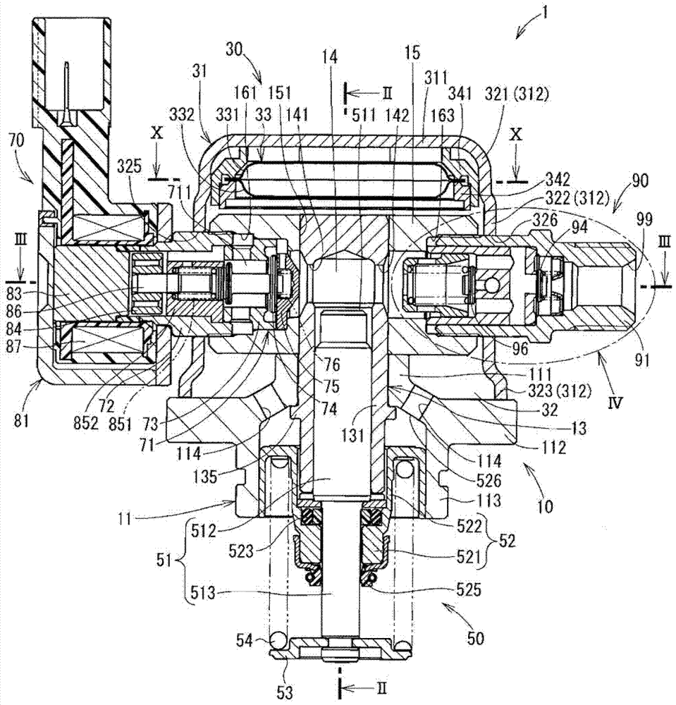
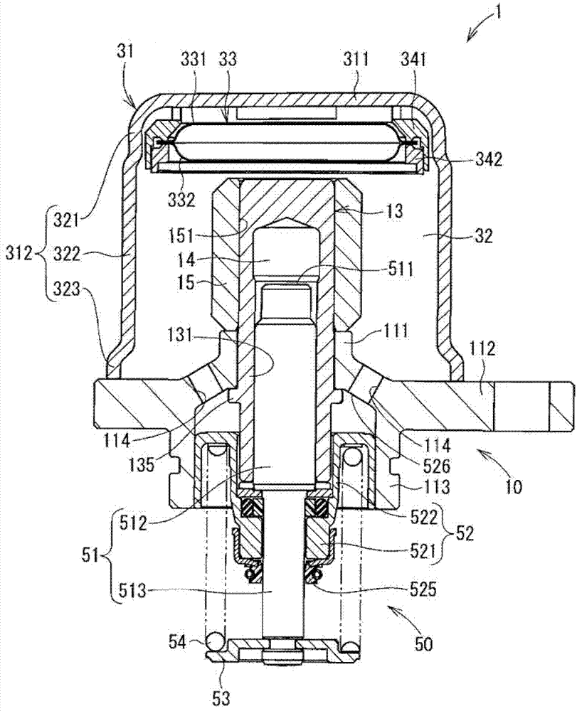
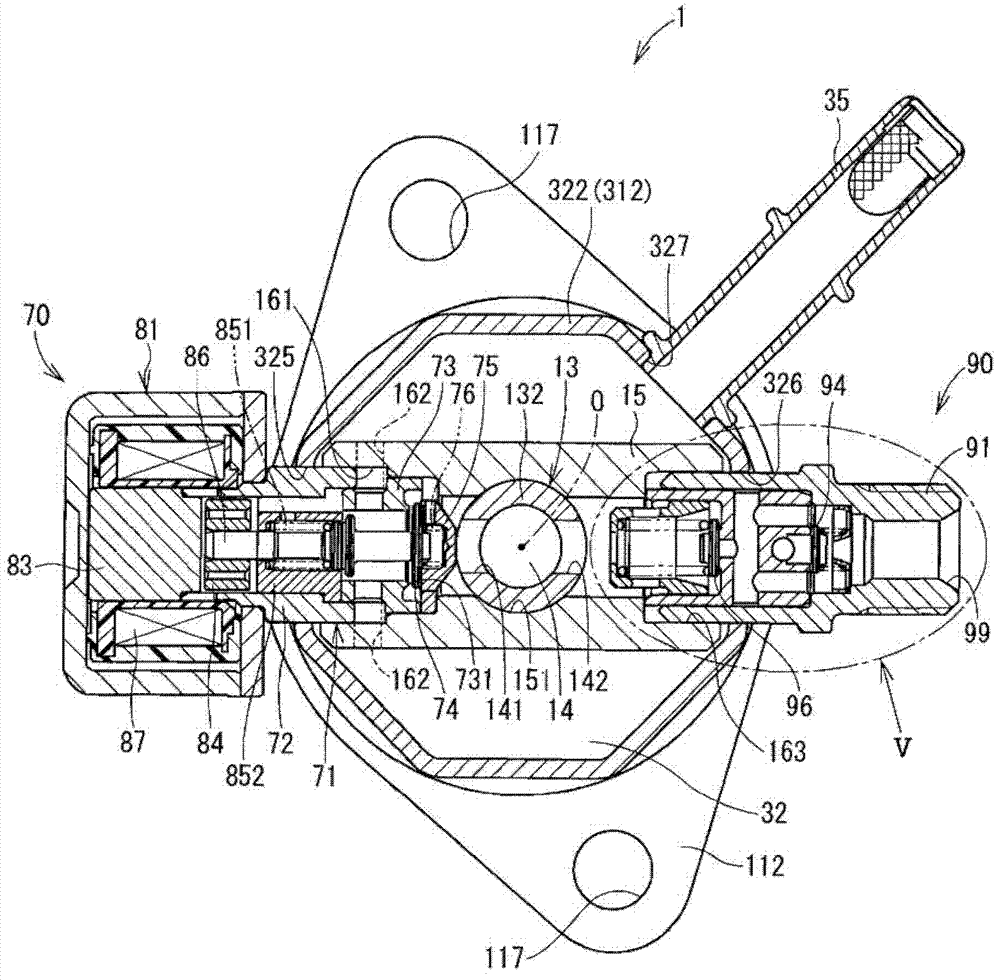
[0040] Figure 1 to Figure 10 A high-pressure pump 1 according to a first embodiment of the invention is shown. The high-pressure pump 1 pressurizes fuel sucked from a fuel tank, and discharges the pressurized fuel to a fuel rail to which a fuel injector is connected. The high-pressure pump 1 includes a main body portion 10 , a fuel supply portion 30 , a plunger portion 50 , a fuel suction portion 70 and a fuel discharge-decompression portion 90 . In the following description, figure 1 The upper side of the will be considered "on", "up" or "upper", figure 1 The lower side of will be considered "under", "down" or "under".
[0041] The main body portion 10 includes a lower housing 11 , a cylinder 13 and an upper housing 15 . The lower housing 11 includes a cylindrical cylinder holding portion 111, an annular flange portion 112 protruding from a lower portion of the cylinder holding portion 111, and a cylindrical engaging portion 113 engaged with an engine (not shown). The f...
no. 2 example
[0088] Figure 11 to Figure 13 A high-pressure pump 1 according to a second embodiment of the invention is shown. In the following embodiments, substantially the same parts and components as those in the first embodiment are denoted by the same reference numerals, and the same descriptions will not be repeated.
[0089] Such as Figure 11 and Figure 12 As shown, an annular gap is formed between the first through hole 325 of the cover 31 and the suction valve body 20 . Furthermore, another annular gap is formed between the second through hole 326 of the cover 31 and the fuel discharge-decompression housing 22 . The suction valve body 20 has an annular first protrusion 21 . The first protrusion 21 is welded to the suction valve body 20 and the cover 31 in such a manner as to close the first through hole 325 .
[0090] The fuel discharge-decompression housing 22 has an annular second protrusion 23 . The second protrusion 23 is welded to the cover 31 in such a manner as to ...
no. 3 example
[0108] The following third to eighth embodiments are partially different from the first embodiment in the shapes of the cover and the upper case. Figure 16 and Figure 17 A high pressure pump according to a third embodiment is shown. The cover 36 of the high pressure pump 2 has a flat portion 311 and a cylindrical portion 361 . The cylindrical portion 361 has a first cylindrical portion 321 and an octagonal portion 322 .
[0109] The octagonal portion 322 has an octagonal cross section. The first through hole 325 and the second through hole 326 are arranged symmetrically with respect to the central axis “O” of the plunger 51 . In addition, if Figure 17 As shown in , the octagonal portion 322 has a third through hole 327 circumferentially adjacent to the second through hole 326 . Cover 36 is welded to flange portion 112 . The cover 31 is made of stainless steel.
PUM
 Abstract
Description
Claims
Application Information