

Multi stage centrifugal pump system
A technology of centrifugal pumps and units, applied in the direction of pumps, pump components, pump devices, etc., can solve the problem of not ensuring continuous injection of liquid
- Summary
- Abstract
- Description
- Claims
- Application Information
AI Technical Summary
Problems solved by technology
Method used
Image

Examples
Embodiment Construction
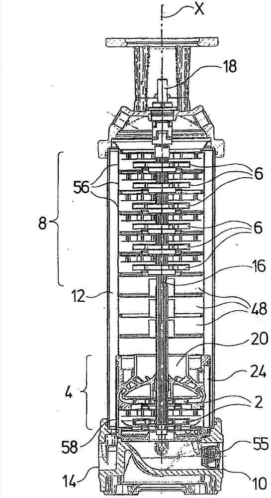
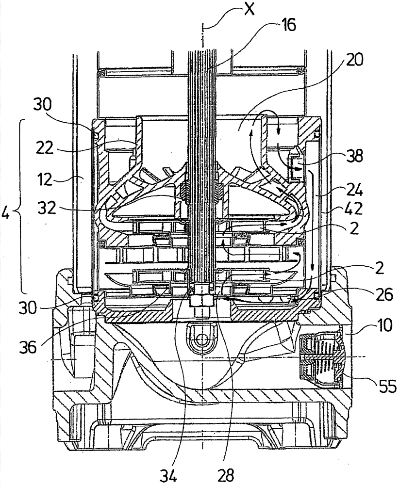
[0055] The centrifugal pump unit shown by way of example has a total of 8 stages, ie 8 impellers. Among them, two impellers 2 are arranged in the first impeller group 4 , and six impellers 6 are arranged in the second impeller group 8 . The first impeller set 4 faces the inlet or suction branch 10 of the pump unit. The second impeller set 8 is connected in series with the first impeller set in the flow or conveying direction. As in known multi-stage centrifugal pump assemblies, the liquid to be conveyed flows successively through the individual impellers and is conveyed from the outlet side of each other to the individual impellers and then from the outlet side of the last impeller 6 through the annular pressure channel 12 to the pressure branch pipe 14. All impellers 2 and 6 are driven by a common shaft 16 . The shaft 16 is connected at its shaft end 18 to an electric motor, not shown here, for example a drive motor.
[0056] The first impeller set 4 is self-priming in th...
PUM
 Abstract
Description
Claims
Application Information