Complete vaporization high temperature combustion boiler

A high-temperature combustion and high-temperature technology, which is applied in the field of atmospheric pressure boilers, can solve the problem of unreasonable combustion furnace heat absorption structure, combustion chamber design structure and even combustion technology. Charcoal and combustible gas cannot get enough oxygen and effectively ignite, combustible gas Can not be effectively ignited and other problems, to achieve the effect of scientific oxygen supply, easy domestic waste, and extended service life

Inactive Publication Date: 2014-09-24
张际新
View PDF7 Cites 0 Cited by
  • Summary
  • Abstract
  • Description
  • Claims
  • Application Information

AI Technical Summary

Problems solved by technology

After the fuel is carbonized, two forms of combustibles, charcoal and combustible gas, are produced. The combustion of these two combustibles requires ignition and oxygen. However, the continuous combustion of traditional combustion methods often prevents charcoal and combustible gas from getting enough oxygen. and effective ignition, only partial, and prone to scorch slag
This is because the traditional combustion method is to supply oxygen from the bottom of the grate for combustion, the charcoal combustion layer is at the bottom, the fuel is on the top, and the air enters from the bottom to meet the charcoal combustion and maintain the combustion layer. When the combustion layer continues to burn, about 60% is consumed Only 40% of the oxygen mixed in the combustible gas enters the upper part, but the entire combustion composition of the fuel, charcoal combustion only accounts for 20% of the deficiency, and the rest of the combustion composition is combustible gas accounting for 80% of the proportion, and 40% of the oxygen is used to meet The combustion of 80% combustible gas is insufficient, so the traditional combustion method is very insufficient, always accompanied by smoke, and carbon monoxide is the main component in the smoke
The second reason why the traditional combustion method cannot burn effectively is that the fuel layer blocks the high temperature so that the combustible gas cannot be ignited effectively. Generally, the thickness of the fuel layer determines the combustion degree of the combustible gas. The thicker the combustible gas is, the harder it is Ignition, practice has proved that the combustible gas can only be ignited if the charcoal combustion layer breaks through the fuel layer, but the fuel layer should also be added after breaking through the fuel layer, which often creates new barriers, so the chimneys that people see are always black smoke
Experiments have proved that insufficient oxygen and ineffective ignition can only make about 40% of the combustible gas combustible, and the remaining 60% is wasted. This is the reason why the traditional combustion method cannot achieve the effect of energy saving and emission reduction
The applicant has invented a number of vaporization combustion technologies in recent years, such as ZL200720013960.7 "Multifunctional Straw Gas Furnace"; ZL200920012920.X "Gas Boiler"; ZL201020510446.6 "Charcoal-Hydrogen Mixed Combustion Double Burner Boiler"; ZL201020510453.6 "Carbonized steam mixed combustion normalization boiler"; ZL201020510448.5 "white heat vaporization double burner civil boiler"; ZL201020510451.7 "carbon hydrogen mixed combustion single burner boiler"; ZL201020510436.2 "carbon hydrogen mixed combustion pressure boiler" and other patents are The applicant has developed the technology in recent years, but there are still many unreasonable things in the heat absorption structure of the combustion furnace, the design structure of the combustion chamber and even the combustion technology

Method used


Image

  • Complete vaporization high temperature combustion boiler
  • Complete vaporization high temperature combustion boiler
  • Complete vaporization high temperature combustion boiler

Examples


Embodiment Construction

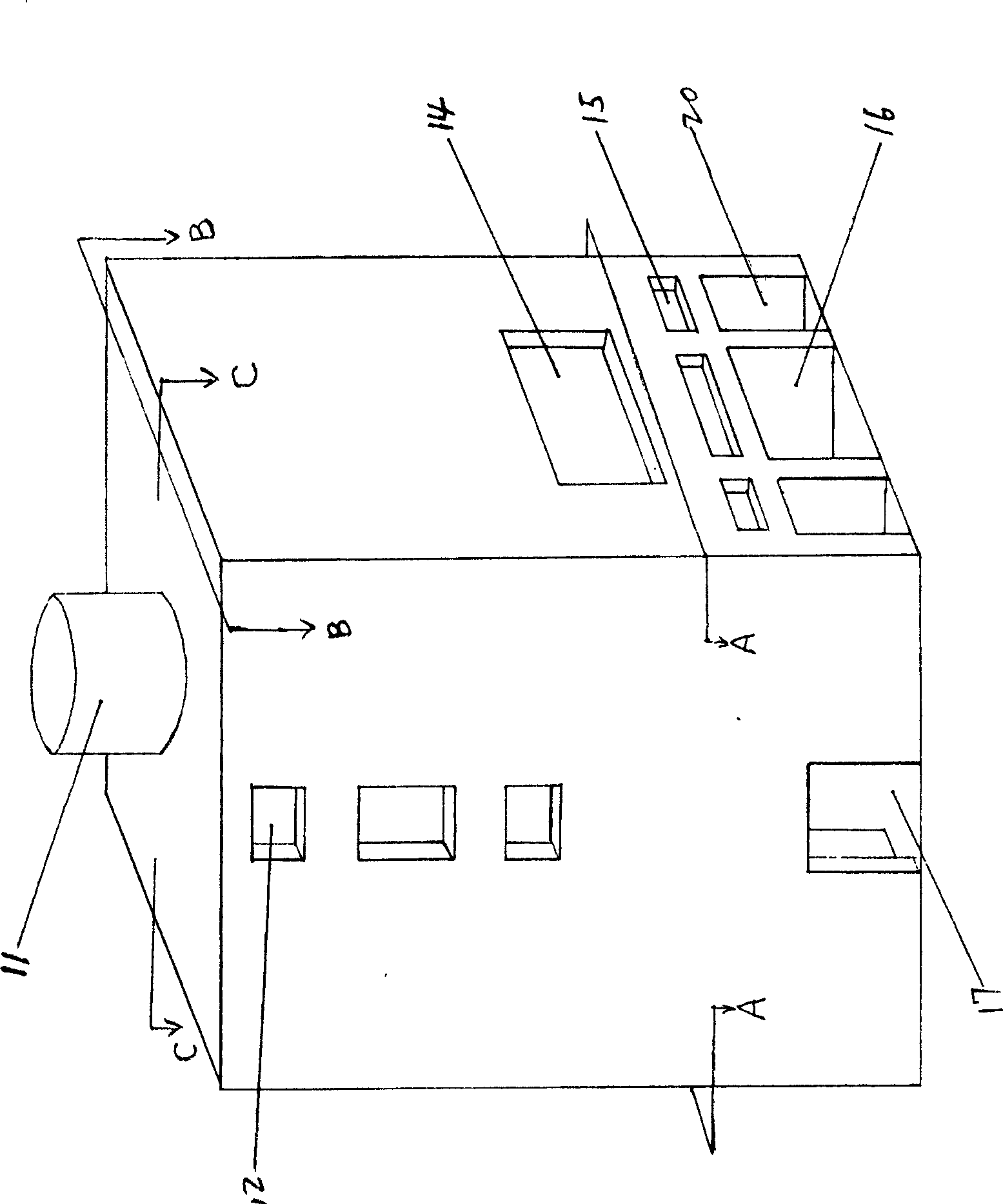
[0018] The specific embodiments of the present invention will be described in detail below in conjunction with the accompanying drawings.

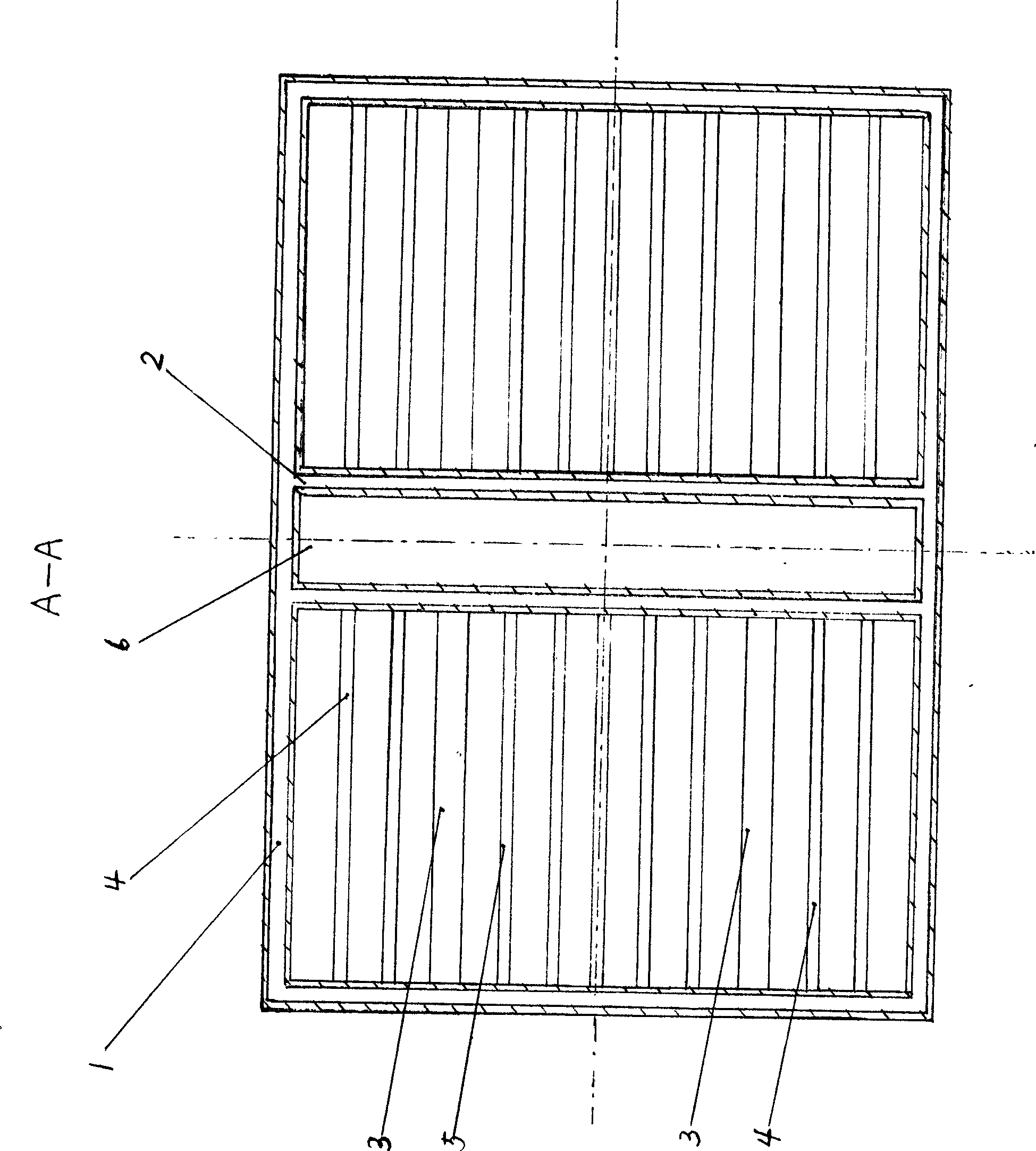
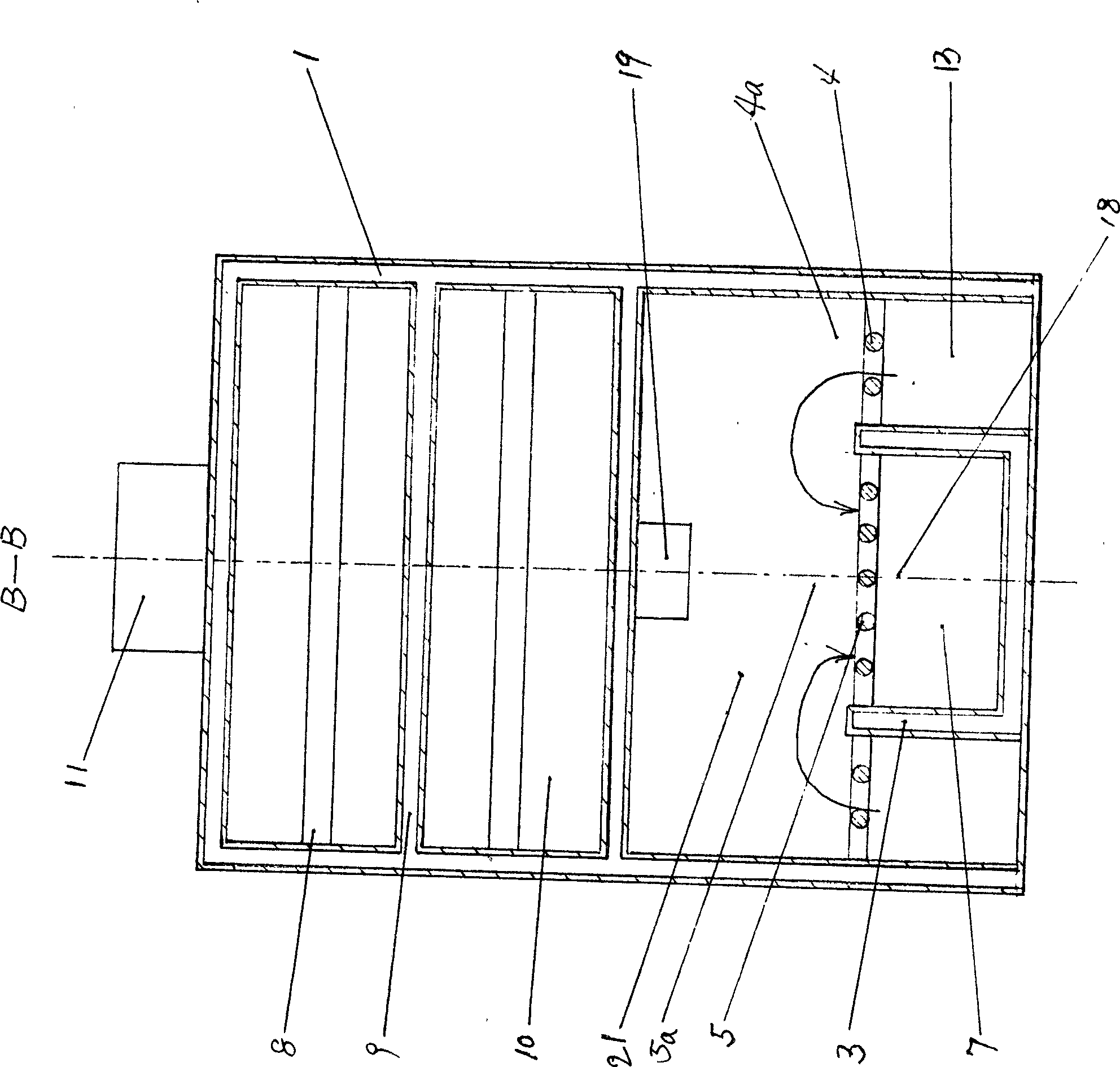
[0019] Such as figure 1 , figure 2 As shown, the structure of the furnace body of the present invention is: two mutually symmetrical combustion chambers 21 are designed in the furnace to be distributed on both sides of the vertical fire channel 6, and the left and right structures are completely symmetrical and the same, and each combustion chamber 21 is divided into steam producing areas 4a and In the high-temperature combustion zone 5a, a furnace grate 4 in the steam-producing zone and a furnace grate 5 in the high-temperature zone are respectively arranged under the steam-producing zone and the high-temperature combustion zone, and the grates in the high-temperature zone are parallel and closely connected to each other; The rear side of the chamber 7 is provided with a fire outlet 18. The fire outlets 18 provided by the two high-tempe...


PUM


Abstract

The invention discloses a complete vaporization high temperature combustion boiler. Two symmetric combustion chambers are distributed on two sides of an upright flame path in the boiler, each combustion chamber is divided into a steam generation area and a high temperature combustion area, a fire outlet extending to the upright flame path is formed in the back side of each high temperature combustion chamber, the upright flame path is defined by upright flame path water jackets, steam generation area grate and high temperature area grate are separated by interval water jackets; a charging oxygen supply gate is arranged above each combustion chamber, a small oxygen supply gate is arranged between the charging oxygen supply gate and the steam generation area grate; an air port above the back side of each combustion chamber is communicated with the upright flame path; and a parallel flame path is arranged above the upright flame path and provided with a steam and fire division water jacket and a steam and fire gathering water jacket. According to the complete vaporization high temperature combustion boiler, all fuel is vaporized, and then the vaporized fuel is subjected to high temperature filter combustion through a high temperature fire layer, so that combustibles such as carbon monoxide, carbon dust and tar cannot be generated, discharge of the combustibles approximates to zero; and moreover, the boiler is strong in fire and large in thermal output, oxygen supply is increased by 1.2 times, the combustion efficiency of the boiler is improved by over 55 percent compared with the combustion efficiency of the conventional boiler, and total carbon emission is reduced by half.

Description

technical field [0001] The utility model relates to an atmospheric pressure boiler using coal and biomass as fuel, in particular to a fully vaporized high-temperature combustion boiler capable of fully burning fuel, high thermal efficiency, heat transfer, large heat absorption area, and fuel saving. Background technique [0002] The structure of the traditional combustion boiler is mostly composed of a furnace body, and the space in the furnace body forms a combustion chamber. There are vents, grates, ash chamber and furnace door under the combustion chamber, and a smoke exhaust pipe is connected to the combustion chamber; The fuel inlet and the combustion chamber in the furnace are arranged with water pipes, and a water return port and a hot water outlet are connected with the water pipes. The combustion method of the traditional furnace body has the following disadvantages: under normal circumstances, the combustion of conventional fuels must go through three stages: one i...

Claims


Application Information

Patent Timeline
Patent Type & Authority Patents(China)
IPC IPC(8): F24H1/44F23B10/02F23B90/04C10J3/20
Inventor 张际新
Owner 张际新
Why Eureka
Try Eureka