Wave energy generation simulation test device

A technology for simulating tests and wave energy, applied in the direction of measuring devices, measuring electricity, measuring electrical variables, etc., can solve the problems of high cost of use, large power consumption, and large area of ​​​​the wave-making pool, so as to reduce the cost of testing and get rid of Site constraints, low cost effects

Inactive Publication Date: 2012-10-17
NINGBO INST OF TECH ZHEJIANG UNIV ZHEJIANG
View PDF9 Cites 19 Cited by
  • Summary
  • Abstract
  • Description
  • Claims
  • Application Information

AI Technical Summary

Problems solved by technology

However, the wave-making pool occupies a large area, consumes a lot of power, and is expensive to use. There are also no specific rules for the real trajectory of the wave, which includes motion in the heave and pitch directions.
However, the wave generated by the

Method used


Image

  • Wave energy generation simulation test device
  • Wave energy generation simulation test device
  • Wave energy generation simulation test device

Examples


specific Embodiment 1

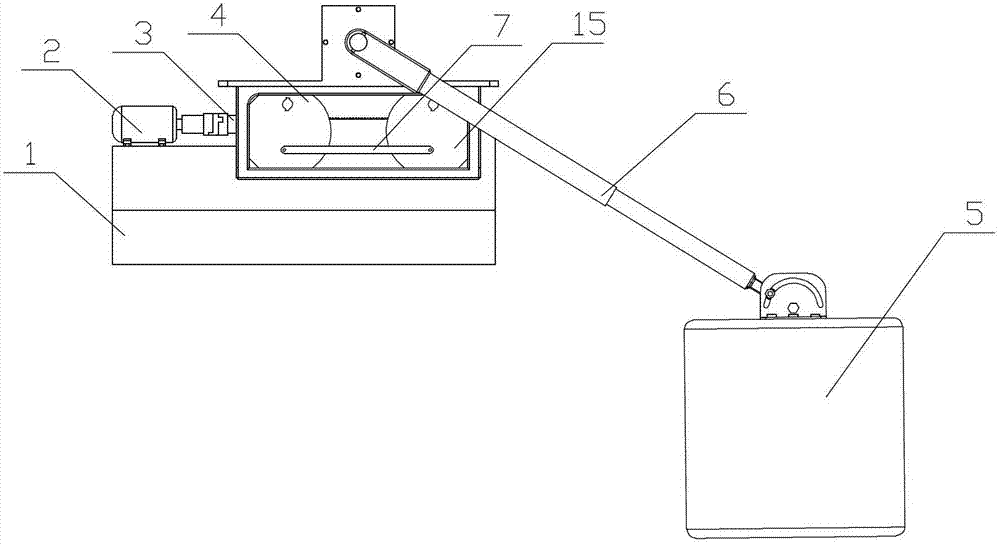
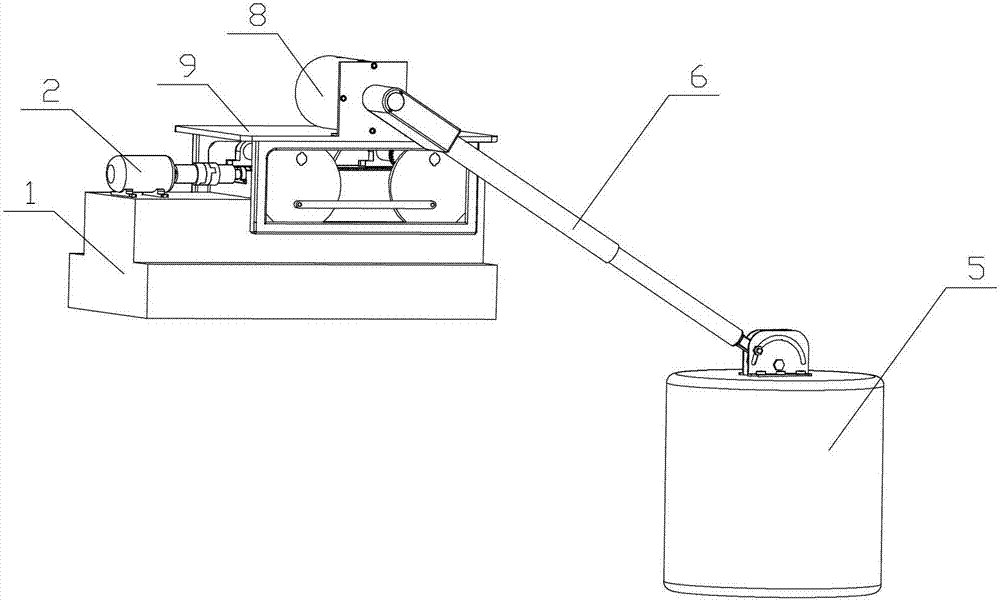
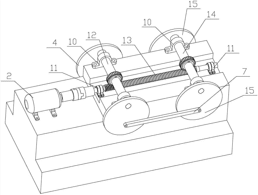
[0024] combined with figure 1 to attach Figure 4, a wave energy power generation simulation test device, which includes a base 1, a motor 2, a transmission rod 13, at least one eccentric wheel, a platen 9, a swing hydraulic cylinder 8 and a buoy 5; the eccentric wheel is connected with an eccentric wheel shaft, and the eccentric wheel shaft passes The bearing seat is installed on the base 1, and the outer peripheral surface of the eccentric wheel is equipped with a guide rail, and the guide rail is provided with a rolling groove. The top of the guide rail is connected with a table 9, and the swing hydraulic cylinder 8 is installed on the table 9. The free end of the swing rod 6 on the cylinder 8 is connected with the buoy 5; the motor 2 is installed on the base 1, and the rotating shaft of the motor 2 is connected in rotation with the described eccentric wheel shaft through the transmission rod 13. Described eccentric wheel is four and is the circular structure of equal diam...

specific Embodiment 2

[0025] further combined with Figure 5 , a wave energy power generation simulation test device, which includes a base 1, a motor 2, a transmission rod 13, at least one eccentric wheel, a platen 9, a swing hydraulic cylinder 8 and a buoy 5; the eccentric wheel is connected with an eccentric wheel shaft, and the eccentric wheel shaft passes The bearing seat is installed on the base 1, and the outer peripheral surface of the eccentric wheel is equipped with a guide rail, and the guide rail is provided with a rolling groove. The top of the guide rail is connected with a table 9, and the swing hydraulic cylinder 8 is installed on the table 9. The free end of the swing rod 6 on the cylinder 8 is connected with the buoy 5; the motor 2 is installed on the base 1, and the rotating shaft of the motor 2 is connected in rotation with the described eccentric wheel shaft through the transmission rod 13. The eccentric wheels are four identical elliptical structures, and the eccentric wheels ...

specific Embodiment 3

[0026] A wave energy power generation simulation test device, which includes a base 1, a motor 2, a transmission rod 13, at least one eccentric wheel, a platen 9, a swing hydraulic cylinder 8 and a buoy 5; the eccentric wheel is connected to an eccentric wheel shaft, and the eccentric wheel shaft passes through a bearing The seat is installed on the base 1, and the outer peripheral surface of the eccentric wheel is equipped with a guide rail, and a rolling groove is provided on the guide rail. The top of the guide rail is connected with a platform 9, and the swing hydraulic cylinder 8 is installed on the platform 9. The free end of the swing rod 6 on the 8 is connected with the buoy 5; the motor 2 is installed on the base 1, and the rotating shaft of the motor 2 is connected to the eccentric wheel shaft through the transmission rod 13 in rotation. further combined with Image 6 , the eccentric wheels are four identical polygonal structures, the eccentric wheels include two fir...


PUM


Abstract

The invention relates to a wave energy generation simulation test device which is characterized by comprising a base (1), a motor (2), a transmission rod (13), at least one eccentric wheel, a bedplate (9), a swinging hydraulic cylinder (8) and a buoy (5), wherein an eccentric wheel shaft is connected to the eccentric wheel and is arranged on the base (1) through a bearing block; a guide rail is matched with outer circumference of the eccentric wheel; a rolling groove is formed on the guide rail; the top of the guide rail is connected with the bedplate (9); the swinging hydraulic cylinder (8) is arranged on the bedplate (9); the free end of a swing rod (6) on the swinging hydraulic cylinder (8) is connected with the buoy (5); the motor (2) is arranged on the base (1); and a rotating shaft of the motor (2) is rotationally connected with the eccentric wheel shaft through the transmission rod (13). The wave energy generation simulation test device is low in cost, can really simulate wave energy generation in a lab environment and is used for performance analysis of a wave energy generation system.

Description

technical field [0001] The invention relates to the technical field of wave energy power generation, in particular to a simulation test device for wave energy power generation. Background technique [0002] With the rapid growth of energy demand and the continuous advancement of science and technology, the development and utilization of ocean energy has become a new hot spot. The ocean contains huge energy sources, such as wave energy, tidal current energy, temperature difference energy, and salt difference energy, all of which are clean and renewable energy sources. Among the actual exploitable amounts of various ocean energies, the utilization and development of wave energy accounts for a considerable proportion. Although the utilization of wave energy has a long history, there are still many problems to be solved in terms of design theory, conversion efficiency, power stability and system reliability of wave energy capture devices. In the prior art, there are many struc...

Claims


Application Information

Patent Timeline
IPC IPC(8): G01R31/00
Inventor 宋瑞银蔡炳清张向阳张美琴
Owner NINGBO INST OF TECH ZHEJIANG UNIV ZHEJIANG
Why Eureka
Try Eureka