Spent fuel storage framework of nuclear power plant

A storage grid and spent fuel technology, applied in nuclear power generation, reactor fuel elements, nuclear engineering, etc., can solve the problems of unfavorable fuel assembly loading and unloading, unfavorable fuel assembly operation, low storage capacity, etc., to achieve easy modular manufacturing Effect

Inactive Publication Date: 2012-10-17
中广核工程有限公司 +1
View PDF13 Cites 21 Cited by
  • Summary
  • Abstract
  • Description
  • Claims
  • Application Information

AI Technical Summary

Problems solved by technology

However, the processing of the bottom plate and upper support plate of the above-mentioned grid is relatively difficult, and the structure of the grid determines that the grid pitch cannot be too small. Therefore, if this structure is applied to the grid in the second zone, it will affect the spent fuel pool. storage capacity
[0004] The structural form and processing of the grid designed by the American HOLTEC company are relatively simple. The neutron absorber material used in this grid is Al-based B 4 C, but the strength of this type of lattice structure is not easy to guarantee
In addition, since there is no guide section on the top of the grid, and there is a boss on the wall of the storage chamber, it is very unfavorable for the operator to insert and insert the fuel assembly, and there is a risk of jamming the operation of the fuel assembly
[0005] The storage grid of the Qinshan Phase I Nuclear Power Plant is in the form of splicing, and the neutron absorber material is suspended. However, the processing of this type of grid is cumbersome, and the fuel consumption credit value of the components is not considered, so the storage capacity is low
The grid of the second area of ​​Ling Ao Nuclear Power Plant is also spliced. It uses boron stainless steel as the structural material, and the grid is made of boron stainless steel plates. Component loading and unloading

Method used


Image

  • Spent fuel storage framework of nuclear power plant
  • Spent fuel storage framework of nuclear power plant
  • Spent fuel storage framework of nuclear power plant

Examples


Embodiment Construction

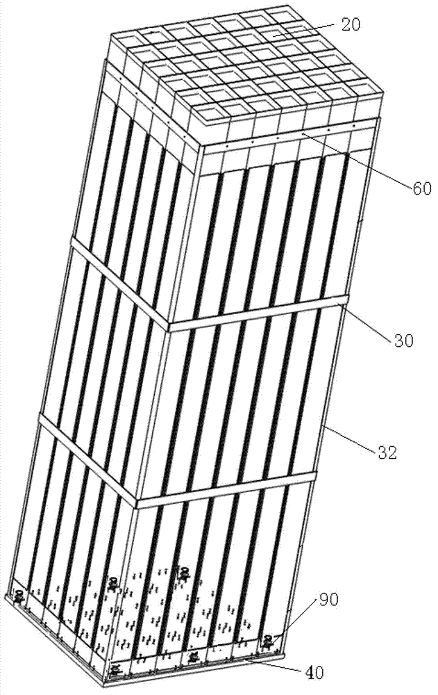
[0027] see figure 1 with figure 2 , The nuclear power plant spent fuel storage grid of the present invention includes a storage chamber 20 , a strip-type fixing structure, a grid bottom plate 40 and a leg assembly 90 .

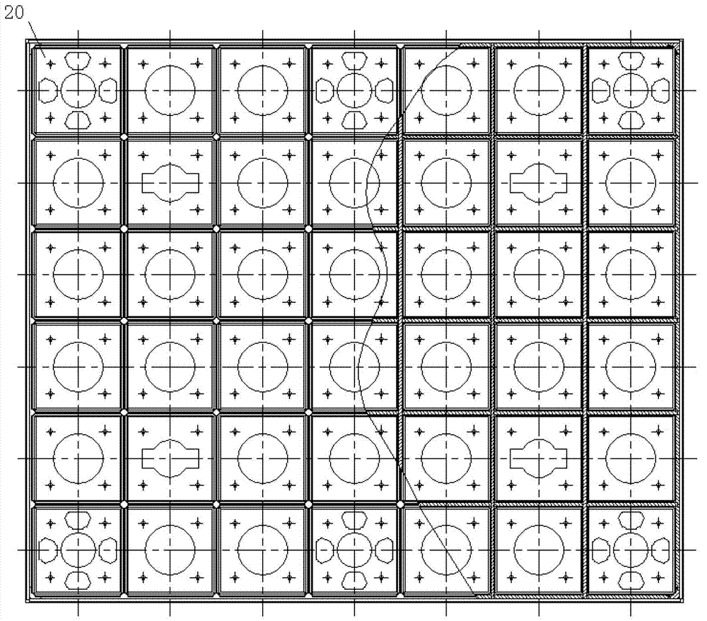
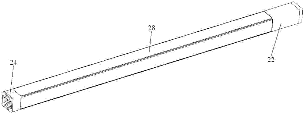
[0028] Please also see Figure 3 to Figure 4 , the storage chamber 20 is an independent storage chamber unit, and each independent storage chamber unit includes a sleeve 22 , a storage chamber base 24 , a neutron absorber and a cladding plate 28 . The sleeve 22 is a square sleeve, and the neutron absorber is fixed on the outer wall of the sleeve 22 through a cladding plate 28, and the whole sleeve 22 is fixed on the storage chamber base 24 which is also a square shape by welding, thereby forming an independent Storage compartment unit. A larger threaded hole 240 is opened in the center of the base 24 of the storage chamber, and four smaller connecting holes 241 and four trapezoidal water holes 242 are opened around it.

[0029] Connecting holes (not shown...


PUM


Abstract

The invention discloses a spent fuel storage framework of a nuclear power plant. The spent fuel storage framework comprises small storage rooms, a framework base plate and supporting leg assemblies, wherein the small storage rooms are independent small storage room units which are fixed on the framework base plate, each independent small storage room unit comprises a sleeve, a small storage room base, an neutron absorber and a coating plate, the sleeves are fixed on the small storage room bases, and the neutron absorbers are fixed on the outer walls of the sleeves through the coating plates. Compared with the prior art, the spent fuel storage framework of the nuclear power plant disclosed by the invention, is combined by the independent small storage room units, and the structures of all the small storage rooms are completely the same, thereby having the characteristic of easiness for modular manufacturing; and the pitch of the framework can be freely regulated as required, and the spent fuel storage framework can be suitable for the neutron absorbers with different thicknesses, meets the storage requirements of various fuel assemblies and is suitable for design requirements of spent fuel storage frameworks in a first area and a second area.

Description

technical field [0001] The invention relates to spent fuel storage technology in nuclear power plants, more specifically, the invention relates to a nuclear power plant spent fuel storage grid with high structural strength and easy processing. Background technique [0002] The nuclear power plant spent fuel storage grid is installed in the spent fuel pool of the fuel building. It is an important equipment for the fuel operation and storage system in the nuclear power plant. Its main function is to safely store fuel components, including irradiated materials discharged from the reactor. Dumped fuel assemblies, spent fuel assemblies that are no longer in the stack, damaged fuel assemblies, and new fuel assemblies (non-irradiated). The difference in enrichment degree of stored fuel assemblies and operating conditions in the stack imposes different requirements on the structure, grid pitch and content of neutron absorber materials of the storage grid. [0003] Existing nuclear ...

Claims


Application Information

Patent Timeline
Patent Type & Authority Applications(China)
IPC IPC(8): G21C19/07
CPCY02E30/30
Inventor 莫怀森张建普林选明何英勇袁呈煜陈楚员陈耀谭经耀辛晓亮马玉杰
Owner 中广核工程有限公司
Why Eureka
Try Eureka