
Spring cable

A spring cable, cable core technology, applied in the direction of insulated cables, cables, circuits, etc., can solve the problems of loss of spring steel wire, increased processing costs, incompatibility, etc., to reduce the concentration of bending stress, low production costs, and avoid localization. damaged effect

Inactive Publication Date: 2012-10-17
FAR EAST CABLE +2
View PDF8 Cites 5 Cited by
  • Summary
  • Abstract
  • Description
  • Claims
  • Application Information

AI Technical Summary

Problems solved by technology

The spring steel wire produced by this process is attached to the inner side of the cable, although the contact with the insulator is reduced, but for the connection between the spring steel wire and the cable, due to the different elastic modulus of the material of the spring steel wire and the cable connection, in the long-term bending and During the stretching process, the fatigue difference between the steel wire and the connecting body will still easily occur, causing the relative displacement of the connecting part to cause fracture, resulting in the separation of the spring steel wire and the cable core, and the loss of the function of the spring steel wire
[0007] In order to solve the problem that the mechanical stress generated by the cable can be evenly distributed on the cable during the contraction and stretching process, instead of applying the mechanical stress to the local point of the cable, the Chinese patent document CN101807779 discloses "A Cable Tray". The traveling distance of the cable is evenly distributed in the hanging wire device, and the connection spring is added to each wire device. The purpose is to use the stretching ability of the spring to evenly distribute the mechanical stress and prolong the service life of the cable. The cost increases, the mechanism is complicated, and this method is only suitable for horizontal back-and-forth movement, not suitable for slope or vertical movement

Method used


Image

  • Spring cable
  • Spring cable

Examples


Embodiment 1

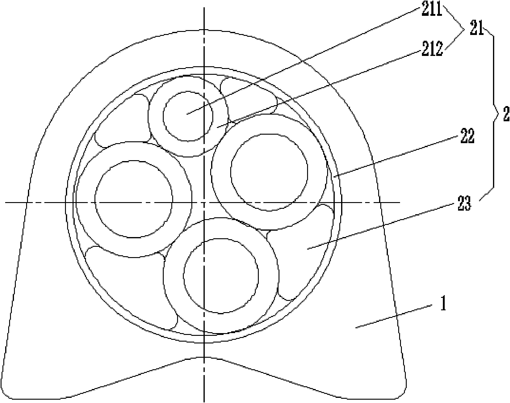
[0031] See figure 1 , the spring cable of this embodiment includes a cable core 2 and a sheath 1 extruded on the outer surface of the cable core 2 .

[0032] The cross-section of the sheath 1 is dovetail-shaped, bounded by the axial plane of the spring cable, the thickness of the lower half is greater than that of the upper half, and the sheath 1 is made of soft PVC material.

[0033] The cable core 2 includes four insulated wire cores 21 , isolation tapes 22 and elastomer filling strips 23 filling the gaps between the insulated wire cores 21 and the isolation tapes 22 . Each insulated wire core 21 includes a conductor 211 and an insulating layer 212 covering the conductor 211; the conductor is a type 5 conductor material, and the insulating layer 212 is an elastomer, which can be selected from natural rubber, ethylene propylene rubber, neoprene and other materials . Four insulated wire cores 21 are twisted into a cable, and the isolation tape 22 is tightly wrapped on the ou...

Embodiment 2

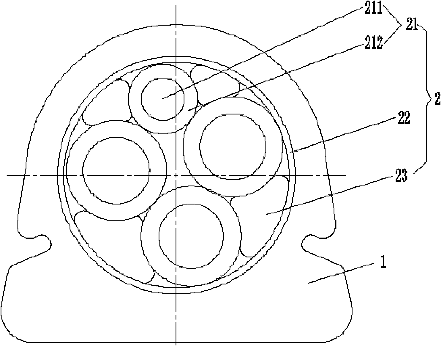
[0036] See figure 2 , the spring cable of this embodiment is basically the same as that of Embodiment 1, the difference is that the cross-section of the sheath 1 is semicircular, bounded by the axial plane of the spring cable, the end face of the lower half is a plane, and in the lower half Grooves are also arranged on the top, and the grooves can assist in absorbing the effect of bending stress and torsional stress generated when the cable is bent.


PUM


Abstract

The invention discloses a spring cable which comprises a cable core and a sheath which is wrapped around an outside surface of the cable core. A cross section of the sheath is not circular, and two parts of the sheath are not asymmetry in shape and have different thicknesses with an axial plane of the spring cable as a boundary. When the cable is bended, the cable always extends or retracts along a position with a weakest stress, thus one end with thicker sheath is always arranged at the inner side during cable bending, when the cable is coiled or loaded to a disk, the end with the thicker sheath retracts at the inner side of the cable automatically, coils and retracts directionally and automatically, a bending stress and a torsional stress generated by the cable can be uniformly distributed on the entire length of the cable, the concentration of the bending stress is reduced, partial damage of the cable is avoided, and a service life of the cable is greatly raised.

Description

technical field [0001] The invention relates to a cable, in particular to a spring cable. Background technique [0002] Spring cables are usually used for vertical and horizontal reciprocating and rotating equipment, such as mobile equipment or lighting power and control lines for film and television stages, audio-visual education, and gymnasiums. During frequent movement, the cable needs to be stored when the device is close to the power line, and stretched out when the device is far away from the power source. In this process, the cable is not only subjected to the pulling or pushing force of the traction, but also the bending stress of the cable and the torsional stress along the axis of the cable. Ordinary spring cables will be wound in random directions during the contraction process, and sometimes the cables will be entangled together, causing the phenomenon that the bending radius of the local point is too small. Due to the frequent crossing of the bending stress and...

Claims


Application Information

Patent Timeline
Patent Type & Authority Applications(China)
IPC IPC(8): H01B7/06H01B7/02H01B7/17
Inventor 陈建忠周峰张洁徐静刘华军
Owner FAR EAST CABLE
Learn More