Displays and Electronics

A display and display function technology, applied in static indicators, instruments, circuits, etc., can solve the problems of display potential fluctuation, pixel circuit electrical influence, and reduce display quality, and achieve the effect of suppressing the deterioration of display quality and reducing electrical influence.

Active Publication Date: 2016-08-03
JOLED INC
View PDF6 Cites 0 Cited by
  • Summary
  • Abstract
  • Description
  • Claims
  • Application Information

AI Technical Summary

Problems solved by technology

[0003] However, in the case where the color filter is provided on the pixel driving substrate, the coloring material included in the color filter may cause a so-called dielectric loss factor and have an electrical influence on the pixel circuit
As a result, the display potential in the pixel circuit fluctuates, causing the inconvenience of lowering the display quality
Furthermore, in a display having a liquid crystal layer driven for display in a horizontal electric field mode, even when the color filter is provided on the opposite plate side, similar inconvenience is caused because the electric field is generated across the color filter

Method used


Image

  • Displays and Electronics
  • Displays and Electronics
  • Displays and Electronics

Examples


no. 1 example

[0048] (Configuration example of organic EL display 1)

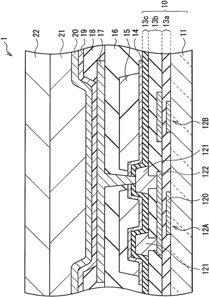
[0049] figure 1 A cross-sectional configuration of the organic EL display 1 according to the first embodiment of the present disclosure is illustrated. The organic EL display 1 has a configuration in which a color filter (color filter 15 ) is provided on the driving substrate 10 side by a so-called COA technique, and causes light emission by a bottom emission (light emitting at the bottom) method. In this organic EL display 1 , for example, a plurality of organic EL devices are arranged on the drive substrate 10 as pixels of R (red), G (green), and B (blue), for example, in a matrix. Note that in figure 1 exemplifies an area corresponding to only one pixel.

[0050] (pixel configuration)

[0051] The drive substrate 10 is a circuit board provided with a pixel drive circuit (described later) that drives the above-described pixels, transistors, and the like. In this drive substrate 10, a transistor section 12A (equivale...

no. 2 example

[0098] Next, a display (organic EL display 2 ) according to a second embodiment of the present disclosure will be described. Elements similar to those of the organic EL display 1 of the first embodiment will be given the same reference numerals as those of the first embodiment, and descriptions will be omitted as appropriate.

[0099] Figure 10 The cross-sectional structure of the organic EL display 2 is illustrated. Like the organic EL display 1 of the first embodiment, the organic EL display 2 has a configuration in which a color filter 15 is provided on the drive substrate 10 side by a so-called COA technique, and has a plurality of organic EL displays that are caused to emit light in a bottom emission method. EL devices serve as pixels. In addition, the configurations of the pixel driving circuit and the pixel circuit are similar to those of the first embodiment.

[0100] In the organic EL display 2, the color filter 15 is provided on the drive substrate 10 like the fi...

no. 3 example

[0107] Next, a display (liquid crystal display 3 ) according to a third embodiment of the present disclosure will be described. In each of the first and second embodiments, an organic EL display has been employed as an example of a display according to an embodiment of the present disclosure, but can also be applied to a liquid crystal display, as will be described below. Note that elements similar to those of the organic EL display 1 in the first embodiment are given the same reference numerals as in the first embodiment, and descriptions will be omitted as appropriate.

[0108] (pixel configuration)

[0109] Figure 13 The cross-sectional configuration of the liquid crystal display 3 is illustrated. For example, the liquid crystal display 3 has a plurality of liquid crystal display devices arranged, for example, in a matrix on the drive substrate 10 as pixels of R (red), G (green), and B (blue). pay attention, Figure 13 Only an area corresponding to one pixel is illustr...


PUM


Abstract

Provided is a display capable of reducing electrical influence of a color filter on a pixel circuit, thereby suppressing deterioration of display quality. The display includes: a pixel driving substrate having a color filter; a display function layer provided on the pixel driving substrate; a first electrode and a second electrode for supplying a driving voltage to the display function layer; to the third electrode of the color filter.

Description

technical field [0001] The present disclosure relates to displays and electronic devices that display color images. Background technique [0002] In image displays such as organic electroluminescence (EL) displays and liquid crystal displays, color filters colored with dyes are provided in display panels for color image display. In recent years, displays using color filter on array (COA) technology, in which such color filters are arranged on a pixel driving substrate, have been developed. [0003] However, in the case where a color filter is provided on a pixel driving substrate, a coloring material included in the color filter may cause a so-called dielectric loss factor and have an electrical influence on a pixel circuit. As a result, the display potential in the pixel circuit fluctuates, causing the inconvenience of lowering the display quality. Furthermore, in a display having a liquid crystal layer driven for display in a horizontal electric field mode, even when col...

Claims


Application Information

Patent Timeline
Patent Type & Authority Patents(China)
IPC IPC(8): G09G3/3233G09G3/36H01L27/32G02F1/1335
CPCG02F1/133514G09G3/3233G09G3/3648G09G2300/0426G09G2300/043G09G2320/0233G09G2320/0242G09G2330/06G02F1/136218H10K59/38H10K59/12
Inventor 寺口晋一尾本启介郡山广久福永容子荒井俊明远藤和之
Owner JOLED INC
Why Eureka
Try Eureka