Drive device for single-phase series commutator motor

A driving device and motor technology, applied in the direction of electric generator/starter, AC motor control, electric motor/converter plug, etc., can solve the problems of resistor heating, large-scale electric tools, etc.

Active Publication Date: 2012-10-17
MAKITA CORP
View PDF8 Cites 8 Cited by
  • Summary
  • Abstract
  • Description
  • Claims
  • Application Information

AI Technical Summary

Problems solved by technology

[0020] However, in the device proposed above, when the braking current reaches a certain upper limit, the both ends of the field winding are connected to the resistor for current consumption, so there is a possibility that the resistor itself will be damaged due to the current flowing through the resistor. problems like fever
[0021] Therefore, in order to put the device proposed above into practical use, it is necessary to implement heat dissipation measures for dissipating the heat generated by the resistor as follows, for example, providing a heat sink for heat dissipation on the resistor, or using a large Resistors, which have the problem of increasing the size of the motor and the electric tool constructed using the motor

Method used


Image

  • Drive device for single-phase series commutator motor
  • Drive device for single-phase series commutator motor
  • Drive device for single-phase series commutator motor

Examples


Embodiment Construction

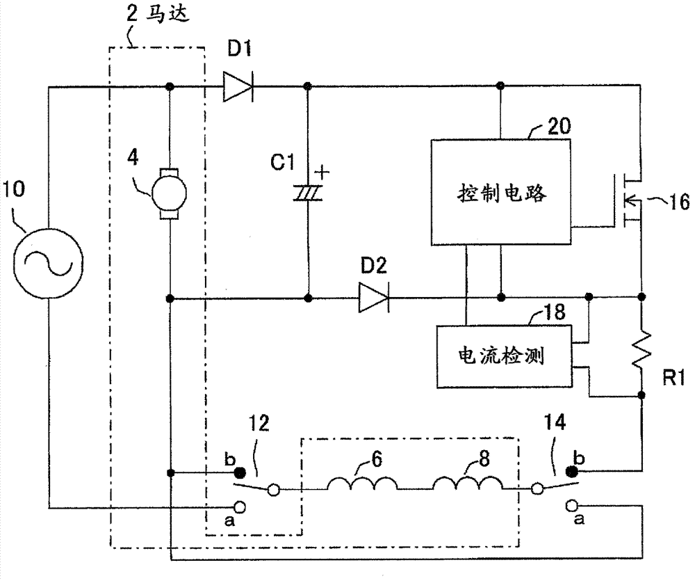
[0051] Hereinafter, the embodiments of the present invention and the appended Figure 1 Same as explanation.

[0052] As shown in FIG. 1, the driving device of this embodiment is a device for receiving power supply from an external AC power source 10 to drive a motor 2 composed of a single-phase series commutator motor. A pair of drive switches 12 and 14 are respectively provided on opposite sides of connection points of field windings (so-called field coils) 6 and 8 (in other words, both ends of field windings 6 and 8 ).

[0053] The motor 2 of this embodiment is used as a power source of an electric tool (such as an electric screwdriver, etc.), and the above-mentioned drive switches 12, 14 are linked with the operation switch of the electric tool. figure 1 On the side of contact b indicated by a black dot, if the operation switch is operated, it switches to figure 1 Side a of the contact point indicated by the white dot.

[0054] Furthermore, when the drive switches 12 an...


PUM


Abstract

A drive device (1) of the present invention includes a pair of drive switches (12, 14), a first diode (D1), a switching element (16), a current detection unit (R1, 18), a capacitor (C1), a second diode (D2), and a current control unit (20). The first diode (D1), the switching element (16), and the current detection unit (R1, 18) are arranged, in this order from one end of an armature (4) in a motor (2), on a braking current path that is formed of the armature (4) and a field winding (6, 8) in the motor (2) when the pair of drive switches (12, 14) is in a brake position. The second diode (D2) is adapted to keep allowing a braking current to flow through the field winding (6, 8) when the switching element (16) is in an off-state by directly connecting a partial path between the switching element (16) and the current detection unit (R1, 18) on the braking current path and the other end of the armature (4).

Description

technical field [0001] The invention relates to a drive device for a single-phase series excitation commutator motor. Background technique [0002] (Outline of single-phase series commutator motor) [0003] A single-phase series commutator motor can be driven rotationally in both DC and AC power sources, and is called an AC-DC dual-purpose motor. Since it can be rotated at a high speed, the influence of the power supply frequency is small, and it can be manufactured at a low cost, it is better utilized for power tools using an AC power supply. [0004] In addition, the single-phase series-excited commutator motor has an armature winding and a field winding connected in series, and when a power supply is connected there, torque is generated and rotational drive is performed. [0005] The characteristic structure of the single-phase series commutator motor is that the generated torque is always fixed in one direction, regardless of the polarity of the AC power supply or the ...

Claims


Application Information

Patent Timeline
Patent Type & Authority Applications(China)
IPC IPC(8): H02P1/16H02P3/06
CPCH02P25/14H02P3/06
Inventor 须田秀和藤波克人
Owner MAKITA CORP
Why Eureka
Try Eureka