X-ray tube

An X-ray tube and X-ray technology, applied in the field of X-ray tubes, can solve problems such as high cost

Inactive Publication Date: 2012-10-17
MICROTEC
View PDF4 Cites 0 Cited by
  • Summary
  • Abstract
  • Description
  • Claims
  • Application Information

AI Technical Summary

Problems solved by technology

[0014] Therefore, in sectors where high output is required (e.g. x-ray inspection of logs), normal market x-ray tubes are not suitable and dedicated, very high output tubes must be used (again at high cost)

Method used


Image

  • X-ray tube
  • X-ray tube
  • X-ray tube

Examples


Embodiment Construction

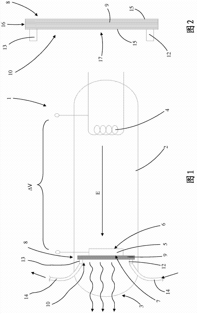
[0026] Referring to the drawings, reference numeral 1 generally denotes an X-ray tube manufactured according to the present invention.

[0027] Similar to prior art X-ray tubes, the X-ray tube according to the invention firstly comprises a closure element 2 which is preferably a glass bulb or the like. The closure element 2 also comprises an emitting part 3, by which the X-rays generated in the tube 1 can be sent towards the area where they are used, for example for X-ray inspection of wood pieces. Such as figure 1 As shown in , a cathode 4 and an anode 5 separated by a space are mounted inside the closure element 2 .

[0028] The cathode 4 can be manufactured in the same way as prior art cathodes. exist figure 1 Among them, in particular, it is a heating coil capable of emitting electrons E due to the thermionic effect.

[0029] On the contrary, similar to the anodes of the prior art, the anode 5 of the present invention is made of a material capable of emitting X-rays wh...


PUM


Abstract

An X-ray tube comprises a containment element (2) in which a cathode (4) and an anode (5) are mounted.The anode (5) comprises a first main face (6) which is substantially facing towards the cathode (4) and a second main face (7) which is facing the opposite way to the first face (6).There are also cooling means (8) applied to the second main face (7) of the anode (5) and filter means (10) for filtering, based on respective wavelengths,the X-rays emitted by the anode (5). The cooling means (8) and the filter means (10) both consist of a heat conductor element (9) which is thermally coupled with the second face (7) of the anode (5) and which is equipped with a plurality of inner micro - channels in which, in practice,a pressurised coolant liquid can flow with a turbulent motion. The containment element also comprises an X-ray emission section (3) positioned in such a way that, in practice,it receives the X-rays emitted from the second main face (7) of the anode (5) after they have passed through the filter means (10).

Description

technical field [0001] The present invention relates to an X-ray tube for generating X-rays, in particular to an X-ray tube capable of generating X-rays with relatively high intensity. The object of the invention is in particular the manufacture of X-ray tubes for use in factories where X-rays are used to inspect wood. Reference is generally made to this sector below. It should be understood, however, that the invention may equally be used in any other sector or for any other purpose. Background technique [0002] Because X-ray tubes were invented more than a century ago, they typically consist of a vacuum vessel (usually a glass bulb) that houses a cathode (negative pole) and an anode (positive pole), and in fact a relatively high DC voltage is applied Between cathode and anode (even a few kV). [0003] The anode is positioned at a predetermined distance from the cathode and includes a heavy disk made of a metal (such as tungsten, molybdenum or rhodium) capable of emitti...

Claims


Application Information

Patent Timeline
IPC IPC(8): H01J35/12G21K1/10
CPCH01J2235/1204G21K1/10H01J2235/087H01J35/12H01J35/116H01J35/13
Inventor G·芬卡尔特
Owner MICROTEC
Why Eureka
Try Eureka