
Stacked secondary battery

A secondary battery, laminated technology, applied in the direction of secondary batteries, secondary battery manufacturing, large flat batteries/batteries, etc., can solve the problems that battery components cannot enter the battery shell, battery components become thicker, and energy density decreases

Active Publication Date: 2012-10-17
ENVISION AESC ENERGY DEVICES LTD
View PDF8 Cites 14 Cited by
  • Summary
  • Abstract
  • Description
  • Claims
  • Application Information

AI Technical Summary

Problems solved by technology

Therefore, although the position accuracy of the electrodes in one bag-shaped separator can be adjusted, when stacking a plurality of positive electrodes, separators, and negative electrodes, the accuracy of the laminated separators is not improved, and stacking misalignment is prone to occur.
[0014] When a battery case is used as a part for accommodating a battery element, if a lamination misalignment occurs in the separator, the thickness of the battery element becomes thick and the battery element may not enter the battery case
In addition, in the case where the laminated film is used as a component for accommodating the battery element, the battery element may become thicker
In this case, although it is possible to accommodate the battery element by increasing the size of the portion of the battery element that accommodates the laminated film by estimating the stacking misalignment in advance, in this case, there will be a problem that the energy density per unit volume will decrease.

Method used


Image

  • Stacked secondary battery
  • Stacked secondary battery
  • Stacked secondary battery

Examples


specific example 1

[0071] The electrode adhesive layer was coated on both sides of a rectangular aluminum foil having a longitudinal length of 94 mm, a lateral width of 64 mm, and a thickness of 20 μm, thereby producing a positive electrode. A current collector tab having a longitudinal length of 30 mm and a lateral width of 10 mm was welded to one short side of the positive electrode.

[0072] The electrode adhesive layer was coated on both sides of a rectangular copper foil having a longitudinal length of 100 mm, a lateral width of 70 mm, and a thickness of 10 μm in order to produce a negative electrode. A collector tab having a longitudinal length of 30 mm and a lateral width of 10 mm was welded to one short side of the negative electrode.

[0073] Thereafter, a plurality of positive electrodes are arranged at predetermined intervals between two belt-shaped separators each having a length of 105 mm. The belt-shaped separators are welded and joined together at intervals along the outer periphery o...

specific example 2

[0081] Except that the negative electrode was not covered with the bag-shaped separator, 50 laminated secondary batteries were produced in the same manner as in the foregoing Specific Example 1.


PUM

PropertyMeasurementUnit
lengthaaaaaaaaaa
widthaaaaaaaaaa
lengthaaaaaaaaaa

Abstract

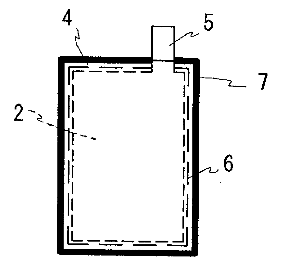
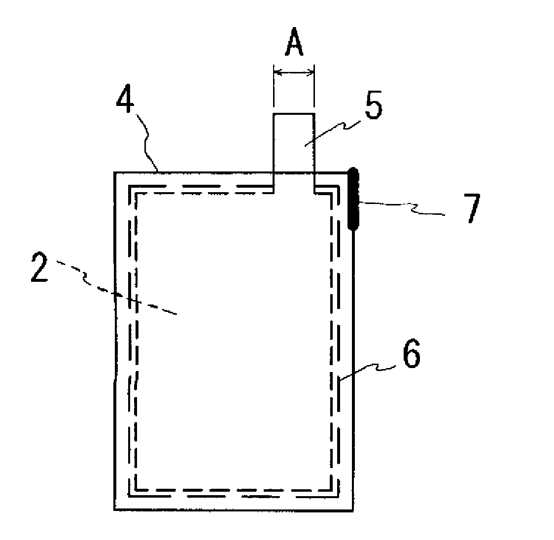
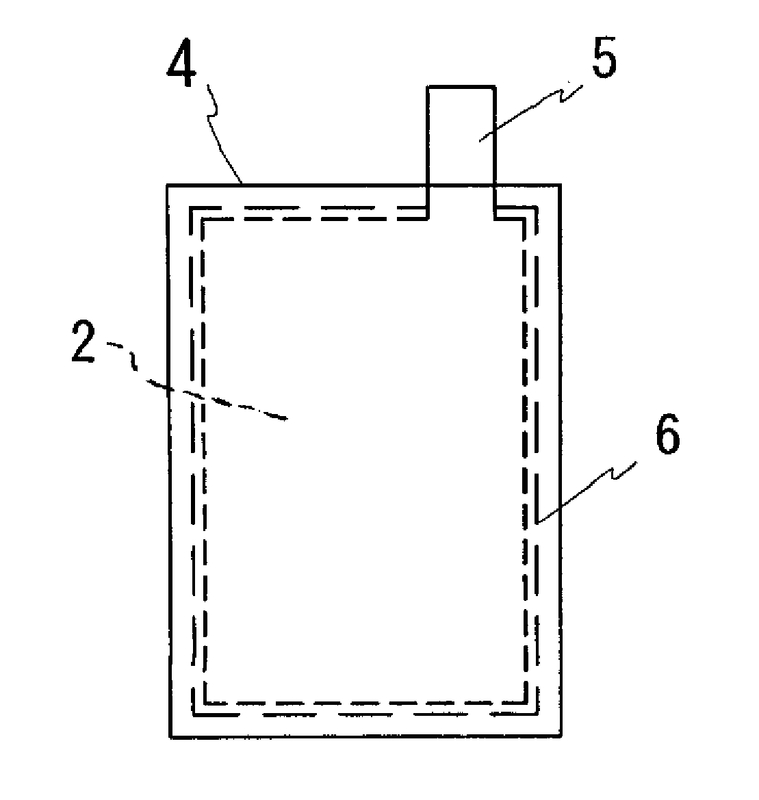
Provided is a stacked secondary battery preventing the occurrence of the wrinkles of a separator and having no electrode-to-electrode and separator-to-separator stacking shifts. The stacked secondary battery has a plurality of flat positive electrodes (2) and negative electrodes (3) stacked alternately and has a plurality of pairs of separators (4'), intermittent bonding portions (6), and an outer circumferential bonding portion (7). The pairs of separators (4') sandwich and cover both the respective positive electrodes (2) and the respective negative electrodes (3) or sandwich and cover either the respective positive electrodes (2) or the respective negative electrodes (3). The intermittent bonding portions (6) are portions where the pairs of separators (4') are bonded and are disposed at intervals along the outer circumference of the positive electrodes (2) or negative electrodes (3). The outer circumferential bonding portion (7) is a portion where outer circumferential parts of the pairs of separators (4') are bonded to each other and are more hardened than any other portions.

Description

Technical field [0001] The present invention relates to a laminated secondary battery. Background technique [0002] Various types of batteries are known. Among them, as batteries with higher energy density, the use of non-aqueous electrolyte batteries such as nickel-cadmium batteries, nickel-hydrogen batteries, lead storage batteries, and lithium-ion batteries is gradually advancing. [0003] Among these batteries, cylindrical batteries, angular batteries, and laminated batteries are known. A cylindrical battery is a battery in which a cylindrical battery element is housed in a battery case, and the cylindrical battery element is manufactured by winding a belt-shaped positive electrode and a negative electrode through a separator. The square battery is a battery in which the battery element manufactured by winding as described above is formed into a flat shape and then housed in a square battery case. A laminated battery is a battery in which a plurality of flat positive electr...

Claims


Application Information

Patent Timeline
Patent Type & Authority Applications(China)
IPC IPC(8): H01M10/04H01M2/18H01M4/02H01M4/13H01M10/0585
CPCY02E60/12Y02E60/122H01M10/0436H01M2/1673H01M10/0413H01M10/0585H01M50/46Y02E60/10Y02P70/50
Inventor 伊势健大道寺孝夫
Owner ENVISION AESC ENERGY DEVICES LTD
Learn More