

Linear cutting suturing device
A suturer and linear technology, applied in the field of medical devices, can solve the problems of high price, difficult processing and assembly, complex structure, etc., and achieve the effect of convenient operation, good promotion value and good performance
Active Publication Date: 2012-10-24
TOUCHSTONE INTERNATIONAL MEDICAL SCIENCE CO LTD
View PDF9 Cites 277 Cited by
- Summary
- Abstract
- Description
- Claims
- Application Information
AI Technical Summary
Problems solved by technology
[0006]The above structures are very complex, difficult to process and assemble, and expensive
Method used
View moreImage
Smart ImageViewing Examples

Examples
Embodiment approach
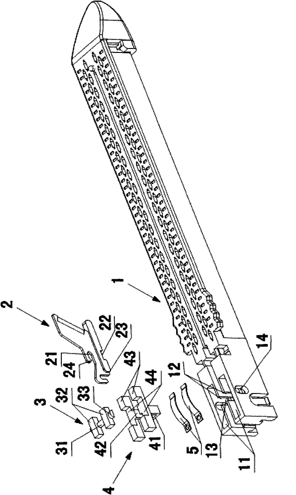
[0056] The present invention still has a variety of embodiments, for example: both sides of the first pressing block 4 are provided with protruding levers (not shown), and the levers are placed in the waist-shaped grooves 14 on both sides of the nail cartridge 1 , the rest of the structure is the same as the above-mentioned embodiment, at this time, the toggling lever can be waved vertically downward manually, so that the linear cutter and stapler is in the fired state.
Login to View More PUM
 Abstract
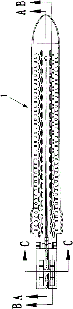
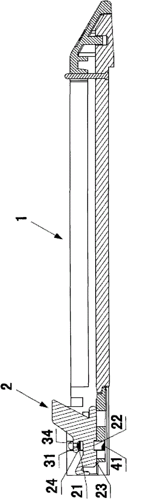
The invention discloses a linear cutting suturing device, which comprises an upper tong clamp and a lower tong clamp, wherein the upper tong clamp and the lower tong clamp can realize the mutual closing or opening, the remote end of the lower tong clamp is provided with a nail cabin, a cutter feeding groove is arranged on the nail cabin in the axial direction, the lower tong clamp is in a U shape, a nail pushing rod and a cutter pushing rod are glidingly arranged inside the lower tong clamp, the remote end of the cutter pushing rod is provided with a cutter, the near end of the nail cabin is provided with a safety mechanism, the safety mechanism comprises a first press block, a triggering mechanism and at least one elastic element, the first press block is arranged in the nail cabin, the bottom end of the cutter is provided with a first notch, and the first notch can realize the longitudinal movement in the nail cabin under the effect of the elastic element and the triggering mechanism, so the first press block and the first notch can be selectively clamped and connected or separated. The linear cutting suturing device has the major beneficial effects that the structure is simple, the processing is convenient, safety and reliability are realized, and good popularization values are realized.
Description
technical field [0001] The invention relates to a linear cutting and suturing device, which belongs to the technical field of medical instruments. Background technique [0002] Linear cutting staplers are widely used in surgical operations for wound suturing, internal tissue suturing and cutting. A typical linear cutting stapler, as disclosed in U.S. Patent No. 5,129,570, has two functions of suturing and cutting. At the same time, excess tissue is removed. This type of linear cutting stapler generally includes upper and lower jaws, and a closing handle for closing the upper and lower jaws. The firing piece and the cutter can be moved relative to the staple cartridge at the same time, and the push button for driving the movement of the firing piece and the cutter. Staples are arranged in the staple cartridge, the firing piece sequentially pushes the staple pusher and pushes the staples to the anvil, and the cutter cuts off the tissue between the staple cartridge and the an...
Claims
Login to View More Application Information
Patent Timeline
 Patent Type & AuthorityApplications(China)
IPC IPC(8): A61B17/072
CPCA61B2017/320052A61B2017/07285A61B17/07207
Inventor陈望东傅开芬
OwnerTOUCHSTONE INTERNATIONAL MEDICAL SCIENCE CO LTD