
Grip type milling and turning composite special blade under extreme super-heavy load condition

A blade, turning and milling technology, applied in the field of turning and milling compound special blades, can solve the problems of blade and chip bonding, blade easy to break, and tool softening, etc., to achieve increased bending and torsional strength, reduced contact area, large The effect of cutting amount

Inactive Publication Date: 2014-01-22
HARBIN UNIV OF SCI & TECH
View PDF44 Cites 1 Cited by
  • Summary
  • Abstract
  • Description
  • Claims
  • Application Information

AI Technical Summary

Problems solved by technology

[0003] The purpose of the present invention is to provide a grip-type turning-milling compound special blade under extreme super-heavy load conditions, so as to solve the phenomenon that a large amount of debris is generated during the cutting process under extreme super-heavy load conditions, the tool is easy to soften, and the blade and chips are bonded. Severe and easy-to-break blade problems

Method used


Image

  • Grip type milling and turning composite special blade under extreme super-heavy load condition
  • Grip type milling and turning composite special blade under extreme super-heavy load condition
  • Grip type milling and turning composite special blade under extreme super-heavy load condition

Examples


specific Embodiment approach 1

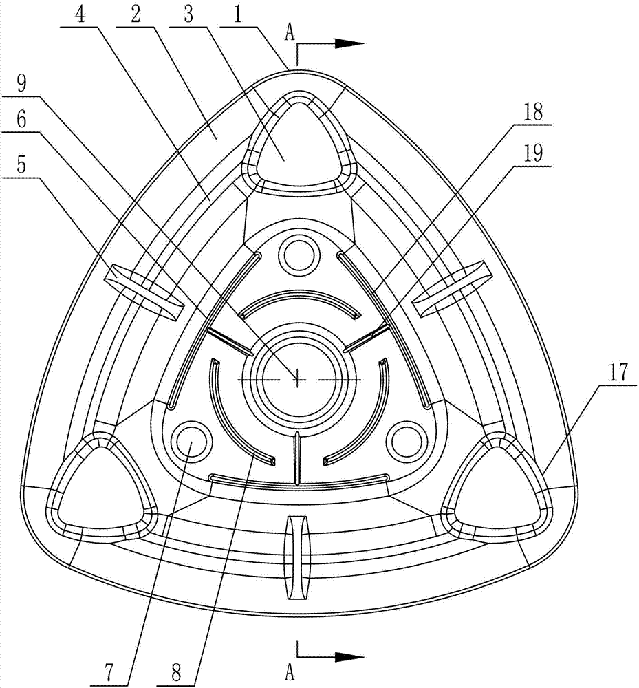
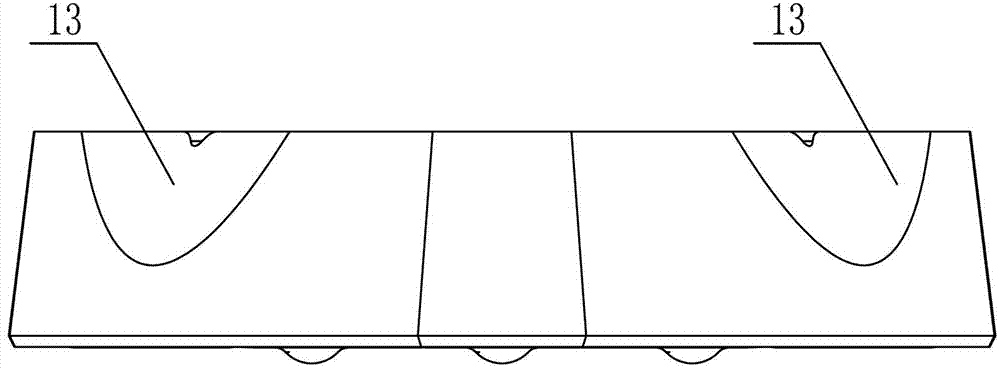
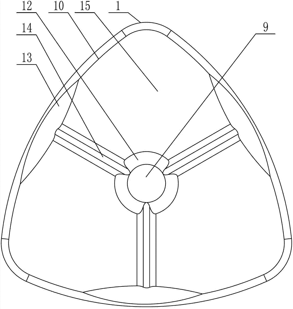
[0009] Specific implementation mode one: combine Figure 1-Figure 6 Explain that a kind of grip-type turn-milling compound special blade under extreme super-heavy load conditions in this embodiment has a shape of a triangular prism, and each side cutter surface 16 of the blade is an arc-shaped side cutter surface protruding outward. , the middle part of the blade is provided with a fastening screw hole 9, the horizontal cross-sectional shape of the blade is an isosceles triangle, the knife point of the blade is located at the intersection of two side knife faces 16 equal in surface area, and the upper knife face 2 and three sides of the blade are The intersections of the two side cutter faces 16 are all processed with a double arc-shaped unequal side negative chamfer cutting edge 11 (the negative chamfer is the prior art), and the middle part of the upper cutter face 2 of the blade is provided with a chip breaking groove 4, which The upper edge of the chip groove 4 is an outwa...

specific Embodiment approach 2

[0012] Specific implementation mode two: combination figure 1 and image 3 Note that the tip of the tool in this embodiment is an arc-shaped tip 1 (mainly considering the mechanical impact load under extremely heavy load conditions, the reason for this design is that the tip of the cutting area is the easiest to break). The undisclosed technical features in this embodiment are the same as those in the first embodiment.

specific Embodiment approach 3

[0013] Specific implementation mode three: combination figure 1 and image 3 Note that the radius of the arc-shaped tool tip 1 in this embodiment is 8-10 mm (which can withstand mechanical impact loads under extremely heavy load conditions). The undisclosed technical features in this embodiment are the same as those in the second embodiment.


PUM


Abstract

The invention provides a grip type milling and turning composite special blade under an extreme super-heavy load condition, which belongs to the technical field of mechanical machining tools. The invention aims at solving problems of the generation of large quantities of chippings, easiness for softening the tool, serious bonding phenomenon between the blade and chips as well as easiness for snapping the blade in the cutting process under the extreme super-heavy load condition at the present. The blade is shaped like a triangular prism; double-arc unequal-side chamfered cutting edges are machined at the intersected parts of the upper blade face and three side blade faces of the blade; a chip breaking recess is formed in the middle of the blade; a boss is arranged at the corner part of the upper blade face of the blade; main and sub cutting edge partition grooves vertical to the double-arc unequal-side chamfered cutting edges are formed in the middle of the double-arc unequal-side chamfered cutting edges; a tightening bolt hole is formed in the middle of the blade; an arc T-shaped recess is formed in the upper blade face of the blade close to the tightening bolt hole; the upper blade face of the blade is provided with a spherical projection and provided with a circular arc groove; a pit is formed in the intersected part of each side blade face and a lower blade face of the blade; and a V-shaped heat radiation groove is formed in the lower blade face of the blade. The grip type milling and turning composite special blade under the extreme super-heavy load condition, provided by the invention, is used for cutting parts under the extreme super-heavy load condition.

Description

technical field [0001] The invention relates to a turning-milling composite special blade, which belongs to the technical field of machining tools. Background technique [0002] Cutting under extremely heavy load conditions means that the blade is subjected to extremely fluctuating mechanical impact loads (cutting force load fluctuation range: 0 to 10 tons) and thermal shock (cutting temperature fluctuation range in the cutting area: 800 ° C to 1000 ° C) under super heavy cutting. Super-large and large-scale nuclear power and petrochemical equiaxed cylindrical parts are directly forged. For example, the cylindrical section is a key component of nuclear reactors and hydrogenation reactors. High temperature resistant special steel The barrel material is a typical wear-resistant and difficult-to-machine material, which has high fatigue resistance, wear resistance, high temperature resistance and thermal toughness. The tube blank is a typical super-large tube part, which is ...

Claims


Application Information

Patent Timeline
Patent Type & Authority Patents(China)
IPC IPC(8): B23B27/00B23C5/02
Inventor 程耀楠何耿煌吴明阳刘利王海婷
Owner HARBIN UNIV OF SCI & TECH
Learn More