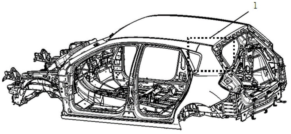
Lap joint structure of top cover rear cross beam and side coaming
A rear crossbeam and connection structure technology, which is applied to the upper structure, upper structure sub-assembly, transportation and packaging, etc., can solve the problems of tailgate rubber strips not being tightly clamped, difficult positioning of parts, and edge interference, etc., to achieve improved torsion Rigidity and anti-side impact performance, simple and reasonable structure, and the effect of increasing structural strength
- Summary
- Abstract
- Description
- Claims
- Application Information
AI Technical Summary
Problems solved by technology
Method used
Image

Examples
Embodiment Construction
[0027] The present invention will be further described below in conjunction with accompanying drawing:
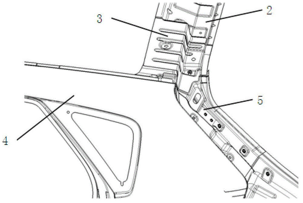
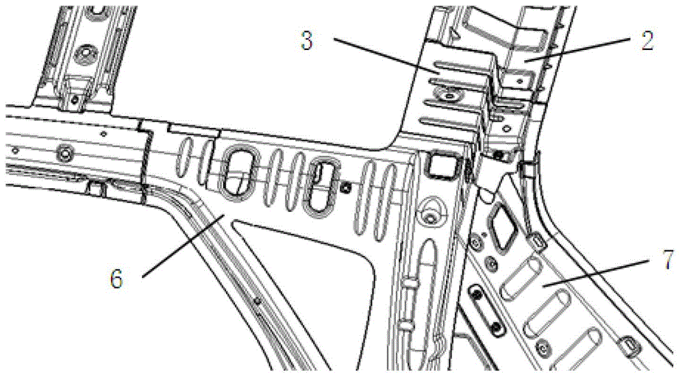
[0028] As shown in the figure, the present invention includes a top cover rear beam 2, a side wall outer panel 4, a water guide plate 5, a rear pillar inner panel angle plate 7, a rear pillar upper reinforcement plate 6 and a top cover outer panel 9, and the top cover rear beam Reinforced version 3 of the back door hinge is welded on the top of 2, the reinforcement plate 6 on the rear pillar is welded together with the reinforcement plate 3 of the back door hinge above the rear beam of the top cover, and the angle plate 7 of the inner panel of the rear pillar of the side wall is welded with the rear beam 2 of the roof cover Together, the top cover outer plate 9 is welded together with the side wall outer plate 4, and the back door hinge reinforcement plate 3 is welded together with the water guide plate 5 on the side wall outer plate assembly. It realizes that the hatchback...
PUM
 Abstract
Description
Claims
Application Information
 - R&D
- Intellectual Property
- Life Sciences
- Materials
- Tech Scout
- Unparalleled Data Quality
- Higher Quality Content
- 60% Fewer Hallucinations
Browse by: Latest US Patents, China's latest patents, Technical Efficacy Thesaurus, Application Domain, Technology Topic, Popular Technical Reports.
© 2025 PatSnap. All rights reserved.Legal|Privacy policy|Modern Slavery Act Transparency Statement|Sitemap|About US| Contact US: help@patsnap.com