
Liquid bottle cap with silica gel valve compressing plunger

A silicone valve and plunger technology, which is applied in the field of container sealing cover structure, can solve the problems of easy opening and liquid can not seep out, etc., and achieve the effect of convenient use.

Inactive Publication Date: 2012-10-24
刘克伟
View PDF3 Cites 1 Cited by
  • Summary
  • Abstract
  • Description
  • Claims
  • Application Information

AI Technical Summary

Problems solved by technology

[0003] this invention In order to overcome the disadvantage that the opening on the silicone valve in the beverage bottle cap with a silicone valve is easy to open when the bottle body is pressurized or the liquid in the bottle is heated and expanded, a method is provided to make the opening on the silicone valve open during transportation. , It is not easy to open during storage, resulting in the structure that the liquid cannot seep out, so that the bottle cap has a better sealing effect

Method used


Image

  • Liquid bottle cap with silica gel valve compressing plunger
  • Liquid bottle cap with silica gel valve compressing plunger

Examples


Embodiment 1

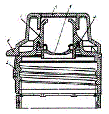
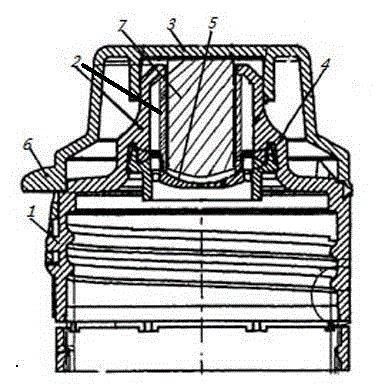
[0017] Embodiment 1: A liquid bottle cap with a compressed silicone valve plunger, including: a bottle cap body 1, a drinking spout 2, a bottle cap cap 3, a valve seat 4 and a silicone valve 5, and the upper part of the bottle cap body 1 is protruding The drinking spout 2, the bottle cap 3 is buckled on the drinking spout 2, the drinking spout 2 is provided with a valve seat 4, the silicone valve 5 is inlaid on the valve seat 4 around, the silicone valve 5 is a silicone gasket with an opening in the middle, and the drinking spout There is a plunger 7 in the mouth 2, and the lower end surface of the plunger 7 is close to the upper surface of the silica gel valve 5 to prevent the liquid in the bottle from penetrating the silica gel valve.

[0018] In Embodiment 1, the shape of the plunger can be any shape that can prevent the liquid in the bottle from entering the drinking spout 2, and the lower end surface of the plunger 7 is in the shape of a straight line or a cross;

[00...

Embodiment 2

[0020] Embodiment 2: A liquid bottle cap with a compressed silicone valve plunger, including: a bottle cap body 1, a drinking spout 2, a bottle cap cap 3, a valve seat 4 and a silicone valve 5, and the upper part of the bottle cap body 1 is protruding The drinking spout 2, the bottle cap 3 is buckled on the drinking spout 2, the drinking spout 2 is provided with a valve seat 4, the silicone valve 5 is inlaid on the valve seat 4 around, the silicone valve 5 is a silicone gasket with an opening in the middle, and the drinking spout There is a plunger 7 in the mouth 2, and the lower end surface of the plunger 7 is close to the upper surface of the silica gel valve 5 to prevent the liquid in the bottle from passing through the silica gel valve, and the opening in the middle part of the silica gel valve 5 is an incision.

[0021] In embodiment 2, if the opening in the middle part of the silicone valve 5 is preferably a vertical cut, it is ensured that the silica gel on both sides of...


PUM


Abstract

The invention relates to a liquid bottle cap with a silica gel valve compressing plunger, which comprises a bottle cap body 1, a drinking nozzle 2, a bottle cap 3, a valve seat 4 and a silica gel valve 5. The protruding drinking nozzle 2 is arranged on the upper part of the bottle cap body 1. The bottle cap 3 is buckled on the drinking nozzle 2 which is internally provided with the valve seat 4. The periphery of the silica gel valve 5 is inlaid on the valve seat 4. the silica gel valve 5 is of a silica gel washer, the middle of which is provided with an opening. The drinking nozzle 2 is internally provided with a plunger 7. The lower end surface of the plunger 7 is clung to the upper surface of the silica gel valve 5 compactly so as to prevent liquid in the bottle from flowing into the drinking nozzle 2 through the silica gel valve 5, especially when the middle opening of the silica gel valve 5 is a vertical cut, the situation that the middle part of the silica gel valve 5 is pushed by the liquid in the bottle to shift and extend the cut in the conveying and storage processes is well avoided, thereby preventing the liquid from entering the drinking nozzle from the cut to be leaked.

Description

technical field [0001] The invention belongs to the technical field of container sealing cap structure, and relates to a beverage bottle cap with a silicone valve, in particular to a structure that prevents the opening of the silicone valve from opening easily. Background technique [0002] The patent name is: Beverage bottle cap with a silicone valve, and the patent number is: 200420011982.6. The Chinese patent discloses a beverage bottle cap with a silicone valve. The liquid will not flow out, which prevents the phenomenon of liquid leakage when the beverage bottle is in a moving state or in a lodging state. But because there is an opening in the middle of the silicone valve, during the transportation and storage process before the bottle cap is opened, when the liquid in the bottle is under pressure on the bottle body, or when the liquid in the bottle is heated and expanded, the liquid in the bottle can easily push the middle of the silicone valve to the drinking spout. ...

Claims


Application Information

Patent Timeline
Patent Type & Authority Applications(China)
IPC IPC(8): B65D51/28
Inventor 刘克伟曹明洲
Owner 刘克伟
Features
  • Generate Ideas
  • Intellectual Property
  • Life Sciences
  • Materials
  • Tech Scout
  • Unparalleled Data Quality
  • Higher Quality Content
  • 60% Fewer Hallucinations
Learn More