Supercharge Your Innovation With Domain-Expert AI Agents!

Belt conveyor longitudinal tear detector and detection method

A belt conveyor, longitudinal tearing technology, applied in the direction of conveyor objects, conveyor control devices, transportation and packaging, etc., can solve the problems of inability to apply belt detection, reduce belt strength, misjudgment, etc.

Inactive Publication Date: 2012-10-24
山西慧达澳星科技有限公司
View PDF9 Cites 28 Cited by
  • Summary
  • Abstract
  • Description
  • Claims
  • Application Information

AI Technical Summary

Problems solved by technology

[0007] The embedded method detection device has great limitations in practical application: first, this type of protection device is complex in process and high in cost; second, it cannot be applied to the detection of a large number of belts that have been installed and running; third, due to the long-term Continuous movement will inevitably produce continuous stress of rolling and shearing, which will cause metal wires, coils or other embedded materials to suffer wear and tear, resulting in misjudgment of detection
However, in a sense, since there is a compatibility problem between the insert and the rubber, if it is not handled properly, it will reduce the strength of the belt
4. Since the detection substance is embedded in the belt, higher requirements are put forward for the maintenance of the belt user
[0013] In summary, there is still no ideal detection method and practical device that can effectively prevent longitudinal tearing.

Method used


Image

  • Belt conveyor longitudinal tear detector and detection method
  • Belt conveyor longitudinal tear detector and detection method
  • Belt conveyor longitudinal tear detector and detection method

Examples


Embodiment Construction

[0032] Below, combined with Figure 1-3 To further describe the present invention in detail.

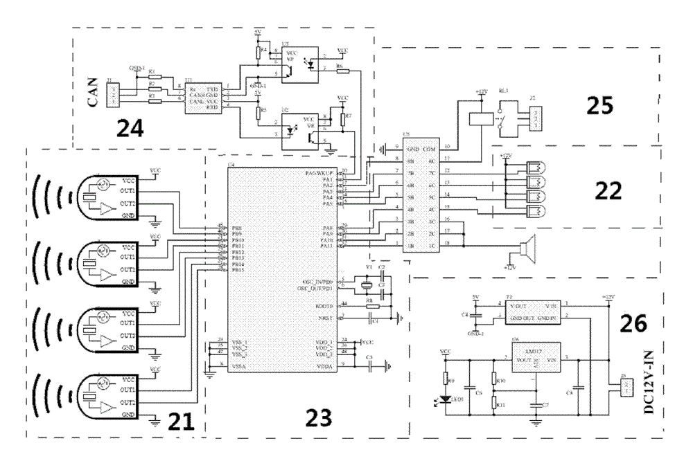
[0033] figure 1 It is the schematic circuit diagram of the ultrasonic sensor and the data processing unit of the embodiment of the present invention. It includes four ultrasonic sensors 21 for measuring the width of the upper and lower belts, four laser emitting units 22 for positioning, a microprocessor unit 23, a communication conversion drive circuit 24, an alarm and control unit 25 and a power supply circuit 26.

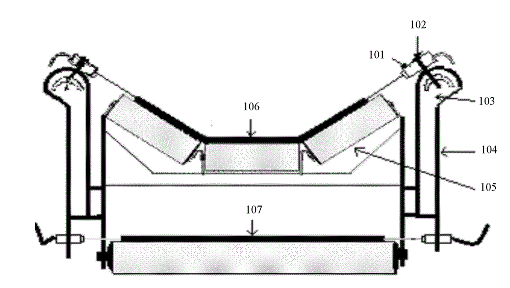
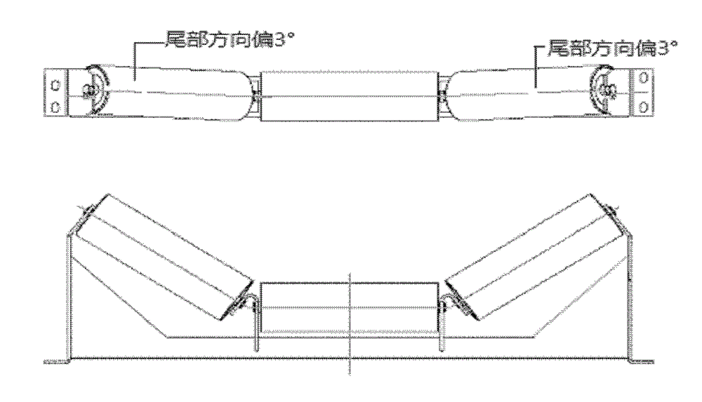
[0034] figure 2 The ultrasonic sensor installation and measurement method of the embodiment of the present invention are given. figure 2 Among them, 101 is an ultrasonic sensor; 102 is a positioning laser head; 103 is a sensor angle adjustment bracket; 104 is a sensor height adjustment bracket; 105 is a belt deflection adjustment bracket; 106 is an upper belt; 107 is a lower belt. Among the four ultrasonic sensors, two are installed on both sides of the upper belt...


PUM

PropertyMeasurementUnit
Angleaaaaaaaaaa

Abstract

The invention relates to a belt conveyor longitudinal tear detector. On the basis of the characteristic that the overall width of the belt correspondingly changes when the longitudinal tear of the belt occurs, a laser positioning technology and an ultrasonic ranging technology are utilized to measure whether the longitudinal tear of the belt occurs and to implement alarm and stop of the belt. On the basis of the belt stress distribution characteristics, a specially designed belt offsetting bracket can pull the belts on the two sides apart to increase the width change, so that the longitudinal tear can be detected more easily. The detection system provided by the invention is composed of a belt offsetting bracket, an ultrasonic sensor, a data processing unit and a computer terminal alarm display, wherein the ultrasonic sensor detects the overall width of the belt; the microprocessor acquires the width data and transmits the width data to the computer terminal through a communication interface, and the computer judges whether the width exceeds a preset value; and if the width exceeds the preset value, the computer terminal sounds the alarm and stops the belt. The historical data can be stored for two years. The detection system provided by the invention not only can prevent the longitudinal tear of the belt conveyor, but also can detect the offsetting and damage condition of the belt. The detection system provided by the invention can work independently or be combined with an existing protection system.

Description

technical field [0001] The present invention relates to a belt conveyor detector and a detection method, in particular to a device that can detect accidents at the initial stage of belt conveyor longitudinal tearing and implement an alarm to avoid large-scale damage to the belt Belt conveyor longitudinal tear detector and detection method. Background technique [0002] Belt conveyors are widely used in ports, mines, steel mills, power plants and other fields. The conveyor belt is an important part of the belt conveyor. The conveyor belt mainly includes ordinary canvas core belts, synthetic fiber core belts, steel rope core belts, etc. With the development of belt conveyors towards high speed, large scale, ultra-long distance, and large inclination angle, steel cord belts are also more and more widely used. Since steel cord belts are expensive and are often used in high-speed, long-distance situations, once the belt is torn in the longitudinal direction, that is, the belt t...

Claims


Application Information

Patent Timeline
IPC IPC(8): B65G43/02
Inventor 张海涛李建平孟绍锋
Owner 山西慧达澳星科技有限公司
Features
  • R&D
  • Intellectual Property
  • Life Sciences
  • Materials
  • Tech Scout
  • Unparalleled Data Quality
  • Higher Quality Content
  • 60% Fewer Hallucinations
Learn More