Differential changeover mechanism for manufacturing battery

A transfer mechanism and battery technology, which can be applied to conveyor objects, transportation and packaging, etc., can solve the problems of complicated equipment, large size, and size restrictions, and achieve the effect of reducing equipment cost, simplifying equipment mechanism, and improving reliability.

Active Publication Date: 2012-10-24
ZHENGJIANG MUSTANG BATTERY CO LTD
View PDF7 Cites 1 Cited by
  • Summary
  • Abstract
  • Description
  • Claims
  • Application Information

AI Technical Summary

Problems solved by technology

In the prior art, the power systems of the embedding machine and the engraving machine are independent of each other. After the embedding, the workpiece needs to be sent to the engraving machine through the lifting feeding mechanism for processing, which leads to the equipment involved in the two processes Complicated and bulky, and the workpiece is prone to failure when it is lifted and transferred
Therefore, the turntable handover mechanism can be considered to solve the above problems, that is, two turntables with equal linear speeds are used to realize the handover of workpieces, and the number of teeth and modules of the two gears driving the two turntables are the same, although this solves part of the problem. , but due to the need to combine the embroidering machine and the engraving machine into one assembly line, the design size of the working table is limited, so the size of the whole system is strictly limited
That is, the existing technology still cannot solve the problem that the ring embedding and scoring equipment are too large

Method used


Image

  • Differential changeover mechanism for manufacturing battery
  • Differential changeover mechanism for manufacturing battery
  • Differential changeover mechanism for manufacturing battery

Examples


Embodiment Construction

[0014] The present invention will be further described below in conjunction with the accompanying drawings and specific embodiments.

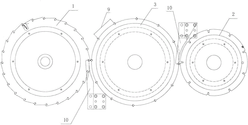
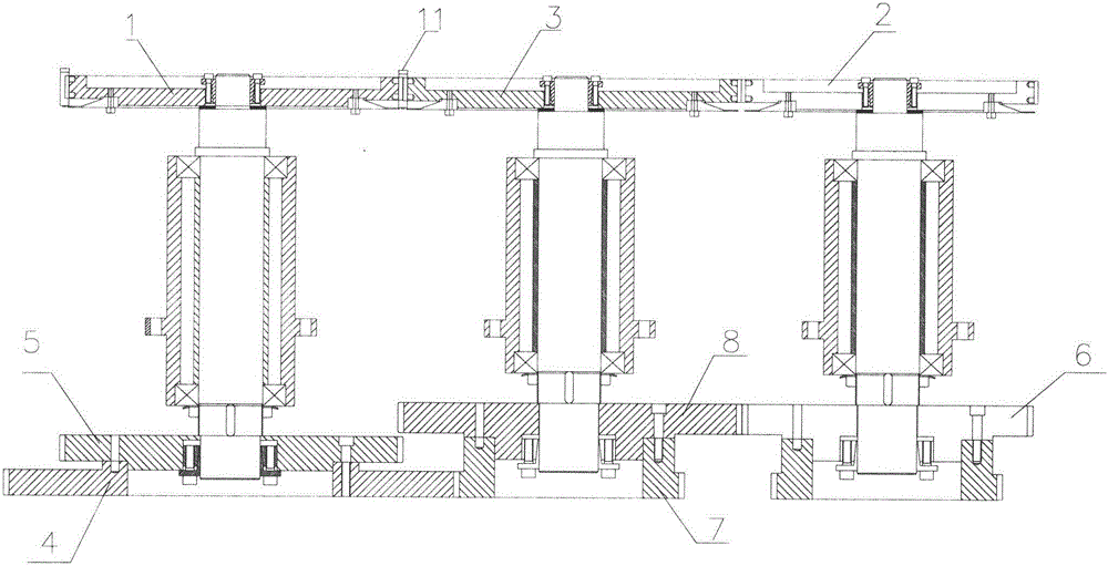
[0015] Such as figure 1 , 2 As shown, the differential transfer mechanism for battery manufacturing of the present invention includes a workpiece disc 1 after the collar, a workpiece disc 2 before scoring and a transfer transition disc 3, and a differential is set on the rotating shaft of the workpiece disc 1 after the collar. The high-speed driving gear 4 and the bezel side gear 5, the engraving side gear 6 is set on the rotating shaft of the workpiece disc 2 before marking, the differential driven gear 7 and the transition gear 8 are set on the rotating shaft of the switching transition plate 3, and the differential driving Gear 4 meshes with differential driven gear 7, and transition gear 8 meshes with engraved side gear 6; the number of teeth of differential driving gear 4 is twice that of differential driven gear 7, and the modulus of the...


PUM


Abstract

The invention discloses a differential changeover mechanism for manufacturing a battery. The differential changeover mechanism comprises a workpiece disk (1) after ring embedding, a workpiece disk (2) before line scribing and a changeover transition disk (3), wherein a revolving shaft of the workpiece disk (1) after ring embedding is provided with a differential driving gear (4) and an embedded ring side gear (5); a revolving shaft of the workpiece disk (2) before line scribing is provided with a line scribing side gear (6); a revolving shaft of the changeover transition disk (3) is provided with a differential driven gear (7) and a transition gear (8); the differential driving gear (4) is meshed with the differential driven gear (7); the transition gear (8) is meshed with the line scribing side gear (6); stations on the workpiece disk (1) after ring embedding are distributed on the circumference of the workpiece disk (1) after ring embedding in the forms of ratchets; and each station on the changeover transition disk (3) is depressed inwardly into a semi-arc groove (9). According to the differential changeover mechanism, combination and effective joint of ring embedding and line scribing procedures are realized, a system is simplified greatly, a huge equipment mechanism is simplified, equipment cost is reduced, and the reliability of equipment is enhanced.

Description

technical field [0001] The invention relates to the field of battery manufacturing, in particular to a differential transfer mechanism for battery manufacturing. Background technique [0002] Ring embedding and scribing are two processes in battery manufacturing. Generally, the ring embedding process is performed first, and then the workpiece is introduced into the scribing equipment for scribing. In the prior art, the power systems of the embedding machine and the engraving machine are independent of each other. After the embedding, the workpiece needs to be sent to the engraving machine through the lifting feeding mechanism for processing, which leads to the equipment involved in the two processes It is complicated and huge, and the workpiece is prone to failure when it is lifted and transferred. Therefore, the turntable handover mechanism can be considered to solve the above problems, that is, two turntables with equal linear speeds are used to realize the handover of wo...

Claims


Application Information

Patent Timeline
Patent Type & Authority Applications(China)
IPC IPC(8): B65G47/52
Inventor 余谷峰胡陈波杨鹏飞徐立
Owner ZHENGJIANG MUSTANG BATTERY CO LTD
Why Eureka
Try Eureka