

Compact material flow adjusting valve
A material flow regulating valve, a compact technology, applied in the directions of sliding valves, valve details, valve devices, etc., can solve the problems of increasing the construction investment of furnace top charging equipment and material consumption costs, high blast furnace top frame, and high structural dimensions. , to achieve the effect of reducing construction investment and material consumption costs, preventing charge segregation, and reducing overall height
- Summary
- Abstract
- Description
- Claims
- Application Information
AI Technical Summary
Problems solved by technology
Method used
Image

Examples
Embodiment Construction
[0022] In the following, the present invention will be specifically described through exemplary embodiments. It is to be understood, however, that elements, structures and characteristics of one embodiment may be beneficially incorporated in other embodiments without further recitation.
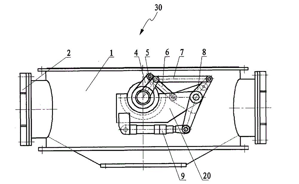
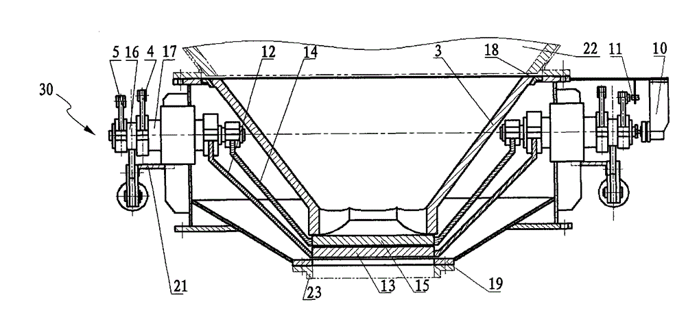
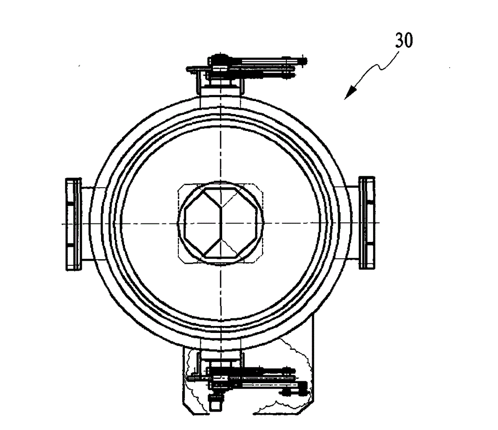
[0023] combine figure 1 as well as figure 2 As shown, the compact material flow regulating valve 30 of the present invention includes: a valve body 1; a manhole door 2, which is correspondingly arranged on the side of the valve body 1; a conical sleeve 18, supported on the valve body body 1; and a liner 3 bearing on said conical sleeve 18. The liner 3 is a wear-resistant conical liner or an eccentric conical liner. Below the liner 3 , there are provided a split-type first valve plate 13 and a second valve plate 15 , and the two valve plates are correspondingly arranged below the liner 3 .
[0024] The compact material flow regulating valve 30 also includes an actuator for driving the fir...
PUM
 Abstract
Description
Claims
Application Information