
Eureka
For R&D, Eureka makes reading and utilizing patents & technical documents easy.
Eureka AIR
Designed for self-driven R&D workflows. Generate viable solutions, solve complex R&D challenges, empower your innovation with AI.

Eureka Materials
Designed for material experts only. Revolutionize your material R&D, from search, analyze, to developing new materials.

TechResearch
Generate reliable direction feasibility study reports for your R&D in just a few steps.

TechSeek
Discover and master advanced knowledge NOW. Basics, ideas, possibilities, all at once.

TechMind
As an expert in R&D Theories, TechMind can generates customized viable solutions instantly.

TechRisk
Analyze your overall solution with one click, know your potential R&D risks in advance.

TechMonitor
Get weekly tech updates, stay abreast of the latest tech innovations and key insights.
Joint assembly
An assembly and joint body technology, applied in the direction of pipes/pipe joints/fittings, adjustable connections, hose connection devices, etc., can solve problems such as easy oil leakage, loose connection devices, and difficult installation
- Summary
- Abstract
- Description
- Claims
- Application Information
AI Technical Summary
Problems solved by technology
Method used
Image

Examples
Embodiment Construction
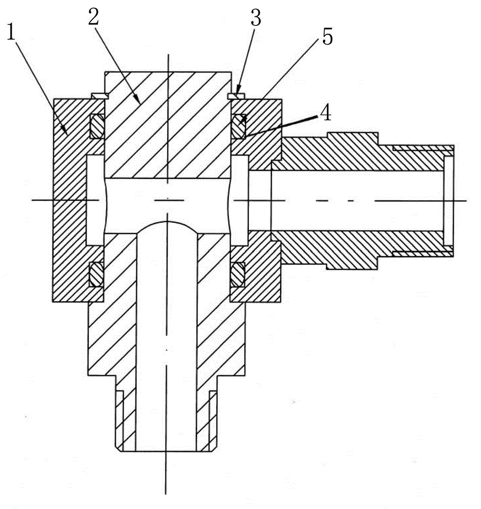
[0009] like figure 1 As shown, the present invention is provided with a cylinder joint body 2 in the oil return pipe joint body 1, and the cylinder joint body 2 and the oil return pipe joint body 1 are connected together by a circlip 3 for the shaft, and the oil return pipe joint body 1 and the cylinder body The pipelines of the joint body 2 are connected, and the upper and lower contact surfaces of the oil return pipe joint body 1 and the cylinder joint body 2 are respectively provided with annular sealing grooves 4 , and O-rings 5 are arranged in the annular sealing grooves 4 . Through the above settings, the cylinder joint body 2 of the present invention is connected to the cylinder head of the piston cylinder, the oil return pipe joint body 1 is connected to the oil return hose, and the hydraulic oil flows through the inner hole of the cylinder joint body 2 through the oil return pipe joint body 1. The oil return hose, when the cargo box is lifted, the oil return pipe jo...
PUM
 Abstract
Description
Claims
Application Information
 - R&D Engineer
- R&D Manager
- IP Professional
- Industry Leading Data Capabilities
- Powerful AI technology
- Patent DNA Extraction
Browse by: Latest US Patents, China's latest patents, Technical Efficacy Thesaurus, Application Domain, Technology Topic, Popular Technical Reports.
© 2024 PatSnap. All rights reserved.Legal|Privacy policy|Modern Slavery Act Transparency Statement|Sitemap|About US| Contact US: help@patsnap.com