Vertical heat exchange type ventilator

A ventilating device, vertical technology, applied in the direction of household heating, heating method, household heating, etc., can solve the problem of unable to meet the installation environment or residential design, and achieve the effect of volume reduction

Active Publication Date: 2014-10-29
北京环都拓普空调有限公司
View PDF8 Cites 0 Cited by
  • Summary
  • Abstract
  • Description
  • Claims
  • Application Information

AI Technical Summary

Problems solved by technology

However, due to various reasons, such a design cannot meet the specific installation environment or residential design

Method used


Image

  • Vertical heat exchange type ventilator
  • Vertical heat exchange type ventilator
  • Vertical heat exchange type ventilator

Examples


no. 1 example

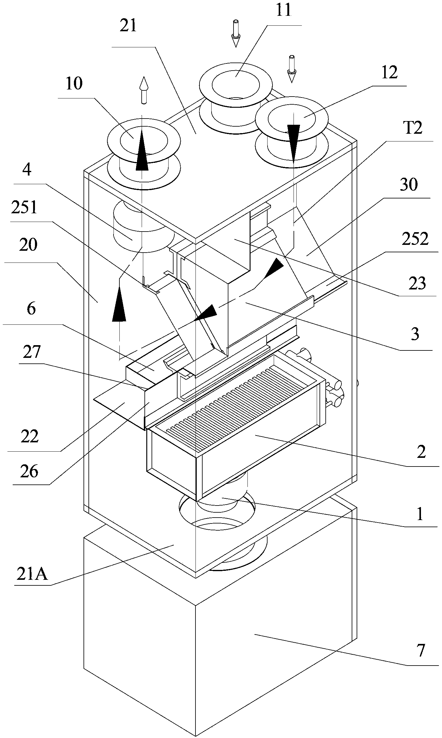
[0027] specific reference figure 1 , the planar isolation plate 22 is located inside the housing and is parallel to the top plate 21 . In the space surrounded by the side plate 20, the top plate 21 and the isolation plate 22, the heat exchanger 3 with a square section, its left corner abuts against the left side of the side plate 20 (the side where the air outlet 10 is located); The line abuts against the right side of the side plate 20 (the side where the return air outlet 12 is located). exist figure 1 In the above, the abutment between the corner line of the heat exchanger 3 and the side plate 20 refers to the abutment through the air duct plate (details will be described later). If necessary, the vertex line of the heat exchanger 3 may be directly in contact with the side plate 20 .

[0028]In the manner of connecting with the four corners of the square section of the heat exchanger 3, a vertical first air channel plate 23 is provided between the top plate 21 and the to...

no. 2 example

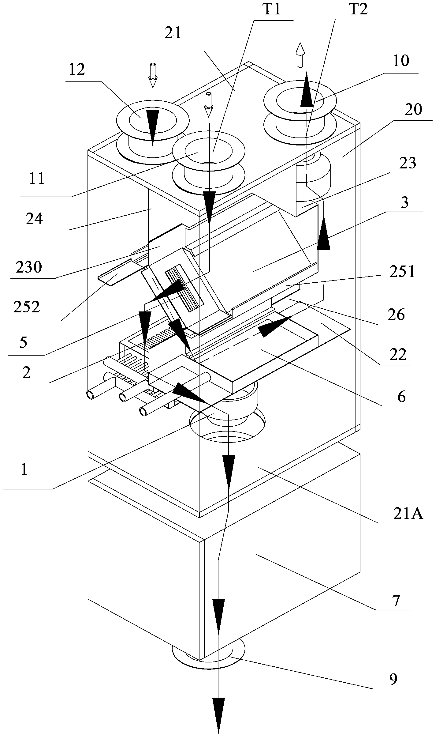
[0051] Figure 4 A structural diagram of a second embodiment of the present invention is schematically shown. Here, the structure of the second embodiment that is different from the first embodiment is mainly described, and the same or similar parts will not be repeated here.

[0052] Such as Figure 4 As shown, the heat exchanger 3 in the second embodiment is connected to the front side plate of the housing, but not to the rear side plate. The air supply part provided on the isolation plate 22 is the air supply port 9 . The fourth air duct plate 252 is connected to the opposite front and rear side plates of the side plates; the third air duct plate 251 is only connected to the front side plate without extending to the rear side plate, and its length is consistent with the length of the heat exchanger 3 . The flow direction of the fresh air is shown by the solid arrow; the flow direction of the return air is shown by the hollow arrow.

[0053] The fresh air on one side of ...

no. 3 example

[0061] Figure 5 A third embodiment of the present invention is schematically illustrated. Here, the structure of the third embodiment that is different from the second embodiment is mainly described, and the same or similar parts will not be repeated here.

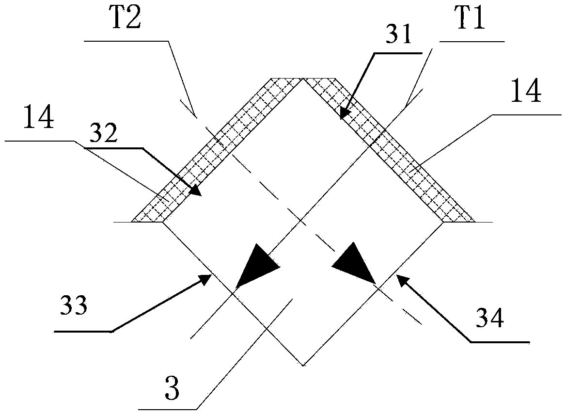
[0062] Such as Figure 5 As shown, the first air channel plate 23 is not connected to the opposite side portions of the side plate 20 , but extends from one side of the side plate 20 to the second air channel plate 24 . The first air duct plate 23 is located between the fresh air port 11 and the return air port 12, and the air outlet 10, and connects the side plate 20 and the top plate 21, and extends downward from the top plate 21 to the fresh air inlet surface 31 and the heat exchanger 3. Air return air intake surface 32 . The first air duct plate 23 is on the same plane as the end surface of the heat exchanger 3 not connected to the side plate 20 .

[0063] The second air channel plate 24 extends from one side of t...


PUM


Abstract

The invention provides a compact vertical heat-exchange air interchanger which comprises a shell, a heat exchanger and a separator, wherein the heat exchanger is arranged inside the shell, and the separator is positioned inside the shell and below the heat exchanger. The shell is provided with a top plate and lateral plates surrounding the top plate, a fresh air inlet and an air outlet are arranged on the top plate, the fresh air inlet is used for leading in fresh air from an outdoor environment, the air outlet is used for exhausting return air to the outdoor environment, and an air supply portion for enabling the fresh air to flow into an indoor environment is arranged on the separator. The compact vertical heat-exchange air interchanger is characterized in that a return air inlet for leading in the return air from the indoor environment is further arranged on the top plate. All components in the shell are compactly arranged, the size of the air interchanger is reduced, an exhaust passage is vertically arranged on the upper portion of the air interchanger in a top entering and top exiting manner, an air supply passage is vertically arranged inside the shell in a top entering and bottom exiting manner, and the air interchanger is suitable for special mounting environments.

Description

technical field [0001] The invention relates to a heat exchange type ventilation device, in particular to a vertical heat exchange type ventilation device, which belongs to the technical field of air conditioning. Background technique [0002] The heat exchange type ventilator is used to ventilate the indoor space. The heat exchange type ventilation device includes a heat exchanger, an air supply channel for supplying fresh air into the room, and an exhaust channel for exhausting indoor air. The air supply channel and the exhaust channel are arranged crosswise, and the heat exchanger is located at the The area where the duct and the exhaust duct cross each other is used for heat recovery of the indoor air discharged from the exhaust duct, and at the same time used to increase the temperature of the fresh air supplied into the room. In winter when the indoor and outdoor temperature difference is large, the heat exchange type ventilation device has a remarkable effect of savi...

Claims


Application Information

Patent Timeline
Patent Type & Authority Patents(China)
IPC IPC(8): F24F7/08F24F12/00F24F13/08
Inventor 张安昌徐国庆张占青
Owner 北京环都拓普空调有限公司
Why Eureka
Try Eureka