Air conditioner and control method thereof

An air conditioner and control device technology, applied in heating and ventilation control systems, heating methods, space heating and ventilation, etc., can solve the problems of no humidity data collection, room temperature and humidity not reaching the expected effect, etc., to achieve convenient and intuitive Understand the effect

Inactive Publication Date: 2012-10-24
HISENSE HOME APPLIANCES GRP CO LTD +1
View PDF4 Cites 6 Cited by
  • Summary
  • Abstract
  • Description
  • Claims
  • Application Information

AI Technical Summary

Problems solved by technology

[0002] Temperature and humidity are important indicators of air conditioning. Existing air conditioners generally only have a temperature sensor (A1) inside the machine. figure 1 As shown, very few air conditioners are equipped with temperature and humidity sensors inside the machine. The air conditioners sampled in the machine have their inherent defects. The temperature and humidity data collected are only the return air data of the air conditioner, not the room temperature that the user wants. Humidity data, so when the air conditioner stops running after reaching the set state, the temperature and humidity of the room did not reach the expected effect
There is also a "portable sense" air conditioner, which is equipped with a temperature sensor inside the machine and on the remote control, but does not collect humidity data outside the machine

Method used


Image

  • Air conditioner and control method thereof
  • Air conditioner and control method thereof
  • Air conditioner and control method thereof

Examples


Embodiment 1

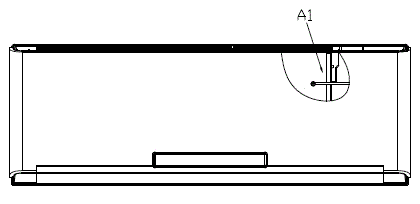
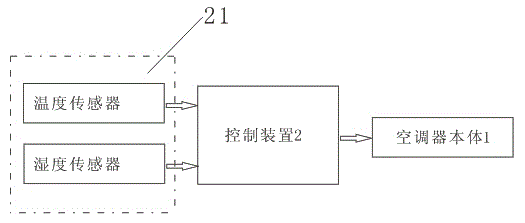
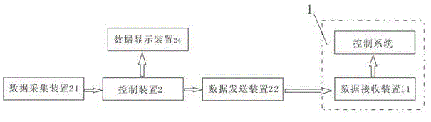
[0027] The structure of the air conditioner of the present invention is as attached figure 2 , 3 , shown in 5 and 6; include the air conditioner body 1 and the control device 2 and the data acquisition device 21 that are arranged on the outside of the air conditioner body 1, the data acquisition device 21 of the present embodiment includes a temperature sensor for detecting indoor temperature and for The humidity sensor for detecting indoor humidity, the signal output end of the temperature sensor and the signal output end of the humidity sensor are respectively connected with the input end of the control device 2, and the air conditioner body 1 is provided with a data receiving device 11, and the data receiving device 11 is connected with the input end of the control device 2. The control system of the air conditioner body 1 is connected, and the control device 2 is also provided with a data transmission device 22 capable of communicating with the data receiving device 11. T...

Embodiment 2

[0036] The air conditioner of this embodiment is similar to Embodiment 1, as Figure 4 As shown, the data display device 24 on the control device 2 is replaced by a speaker 23. The speaker 23 in this embodiment is a speaker. The temperature and humidity data processed by the control device 2 are notified to the user in the form of sound through the speaker, and will be transmitted to the user at the same time. Air conditioner body 1.


PUM


Abstract

The invention discloses an air conditioner and a control method thereof. The air conditioner comprises an air conditioner body, a control device and a data collecting device arranged outside the air conditioner body; the data collecting device comprises a temperature sensor; the signal output end of the temperature sensor in the data collecting device is connected with the input end of the control device; the data collecting device further comprises a humidity sensor for detecting an indoor humidity; and the signal output end of the humidity sensor is connected with the input end of the controller. When the air conditioner operates, the control device judges temperature and humidity data respectively collected by the external temperature sensor and humidity sensor through user-defined conditions, so as to determine an environment condition of air; furthermore, the data is fed back to the air conditioner body, and the air conditioner body determines an operation condition according to the fed data. With the adoption of the air conditioner, the problem that the environment temperature and humidity judged by the conventional air conditioner have a difference with the environment temperature and humidity thought by a user can be solved, so that the user can conveniently and intuitively know about the temperature and humidity state of indoor air.

Description

technical field [0001] The invention relates to the technical field of air conditioners in electrical equipment, in particular to an air conditioner and a control method thereof, and belongs to the improvement technology of the air conditioner and the control method thereof. Background technique [0002] Temperature and humidity are important indicators of air conditioning. Existing air conditioners generally only have a temperature sensor (A1) inside the machine. figure 1 As shown, very few air conditioners are equipped with temperature and humidity sensors inside the machine. The air conditioners sampled in the machine have their inherent defects. The temperature and humidity data collected are only the return air data of the air conditioner, not the room temperature that the user wants. Humidity data, so when the air conditioner stops running after reaching the set state, the temperature and humidity of the room did not achieve the expected effect. There is also a "porta...

Claims


Application Information

Patent Timeline
Patent Type & Authority Applications(China)
IPC IPC(8): F24F11/02
Inventor 李德鹏王磊李宗怀杨志健邓广森袁兴建
Owner HISENSE HOME APPLIANCES GRP CO LTD
Why Eureka
Try Eureka