Light transmission scanning-detecting controlling method for ceramic antenna cover

A technology of ceramic antenna and transmission scanning, which is applied in the direction of digital control, electrical program control, optical test flaws/defects, etc. It can solve the problems of easy fatigue of human eyes, inability to guarantee detection accuracy, and inability to guarantee the final quality of products, etc., to achieve judgment The effect of accurate results and precise detection results

Inactive Publication Date: 2012-10-24
SHANDONG UNIV OF TECH
View PDF7 Cites 5 Cited by
  • Summary
  • Abstract
  • Description
  • Claims
  • Application Information

AI Technical Summary

Problems solved by technology

In the current inspection of thin-walled ceramic radome products, the above-mentioned defects are detected by inspectors through the transmission light source and human eye observation. Workers work in a highly tense and continuo...

Method used


Image

  • Light transmission scanning-detecting controlling method for ceramic antenna cover
  • Light transmission scanning-detecting controlling method for ceramic antenna cover
  • Light transmission scanning-detecting controlling method for ceramic antenna cover

Examples


Embodiment Construction

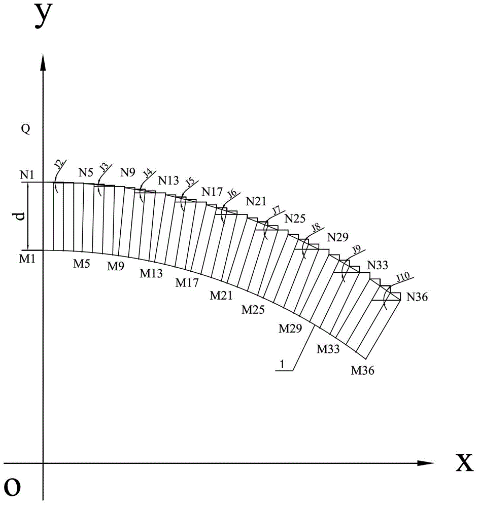
[0024] To detect the ceramic radome 1 with a bottom circle radius of 200mm and a cone height of 500mm, first set the system coordinate system: take the central axis of the ceramic radome 1 as the y-axis, and take the radius of the bottom circle passing through the ceramic radome 1 as the x-axis , take the radius of the bottom circle perpendicular to the x-axis as the z-axis, and the origin of the coordinates is O, and then perform the following steps:

[0025] Step 1): If figure 1 As shown in , by adjusting the position of the laser ranging image acquisition head in the coordinate system, it is located at point Q at a certain distance above the top of the ceramic radome 1, and the laser emitting direction of the laser ranging image acquisition head is aligned with the ceramic radome The normal line at the vertex of 1 is parallel, adjust the distance from the laser ranging image acquisition head to the surface of the ceramic radome 1, when the image collected by the laser rangi...


PUM


Abstract

The invention relates to a light transmission scanning-detecting controlling method for a ceramic antenna cover. The light transmission scanning-detecting controlling method comprises the following steps of: (1) locating a coordinate position of a starting point of a laser ranging image collection head; (2) measuring a starting coordinate position of a scanning control point through focusing; (3) determining a coordinate position of the scanning control point of an antenna cover and a scanning incidence angle according to a method selected by track calculation and equal error control points; (4) calculating a light source coordinate moving position according to the scanning incidence angle of each scanning control point; (5) carrying out compiling of a scanning control NC program on a scanning path, a scanning incidence angle and a light source according to a line point position control mode; (6) calculating according to a visual angle of a laser ranging image acquisition head and a scanning row central section outer edge curve to compile a circular scanning NC program; and (7) controlling the laser ranging image acquisition head to carry out image acquisition on the antenna cover and carry out processing and analyzing to obtain crack and loose texture defect parameters of the ceramic antenna cover to be used for quality judgment.

Description

technical field [0001] The invention relates to a light transmission scanning detection control method of a ceramic radome, which belongs to the technical field of non-destructive testing. Background technique [0002] After production, thin-walled ceramic radome products inevitably have defects such as cracks, loose texture, and holes. In the current inspection of thin-walled ceramic radome products, the above-mentioned defects are detected by inspectors through the transmission light source and human eye observation. Workers work in a highly tense and continuous working environment, and human eyes are prone to fatigue, and there is no guarantee The accuracy of the detection cannot obtain accurate and quantitative detection results. Such a detection method cannot guarantee the final quality of the product. Contents of the invention [0003] The object of the present invention is to provide a ceramic radome light transmission scanning detection control method that can ove...

Claims


Application Information

Patent Timeline
IPC IPC(8): G05B19/18G01N21/88
Inventor 赵玉刚李业富王勇
Owner SHANDONG UNIV OF TECH
Why Eureka
Try Eureka