
Battery

A battery and cell technology, applied in secondary batteries, battery pack components, circuits, etc., can solve problems such as uneven internal temperature, poor battery performance, and uncontrollability, to ensure working performance, improve cycle performance, eliminate The effect of temperature difference

Active Publication Date: 2012-10-24
BYD CO LTD
View PDF6 Cites 9 Cited by
  • Summary
  • Abstract
  • Description
  • Claims
  • Application Information

AI Technical Summary

Problems solved by technology

[0004] In order to solve the disadvantages of the existing battery such as uneven and uncontrollable internal temperature during operation, and poor performance and instability of the battery under complex working conditions, the present invention provides a uniform and controllable internal temperature, which can keep the battery in a relatively high temperature at the same time. Battery in good working condition

Method used


Image

  • Battery
  • Battery
  • Battery

Examples


Embodiment 1

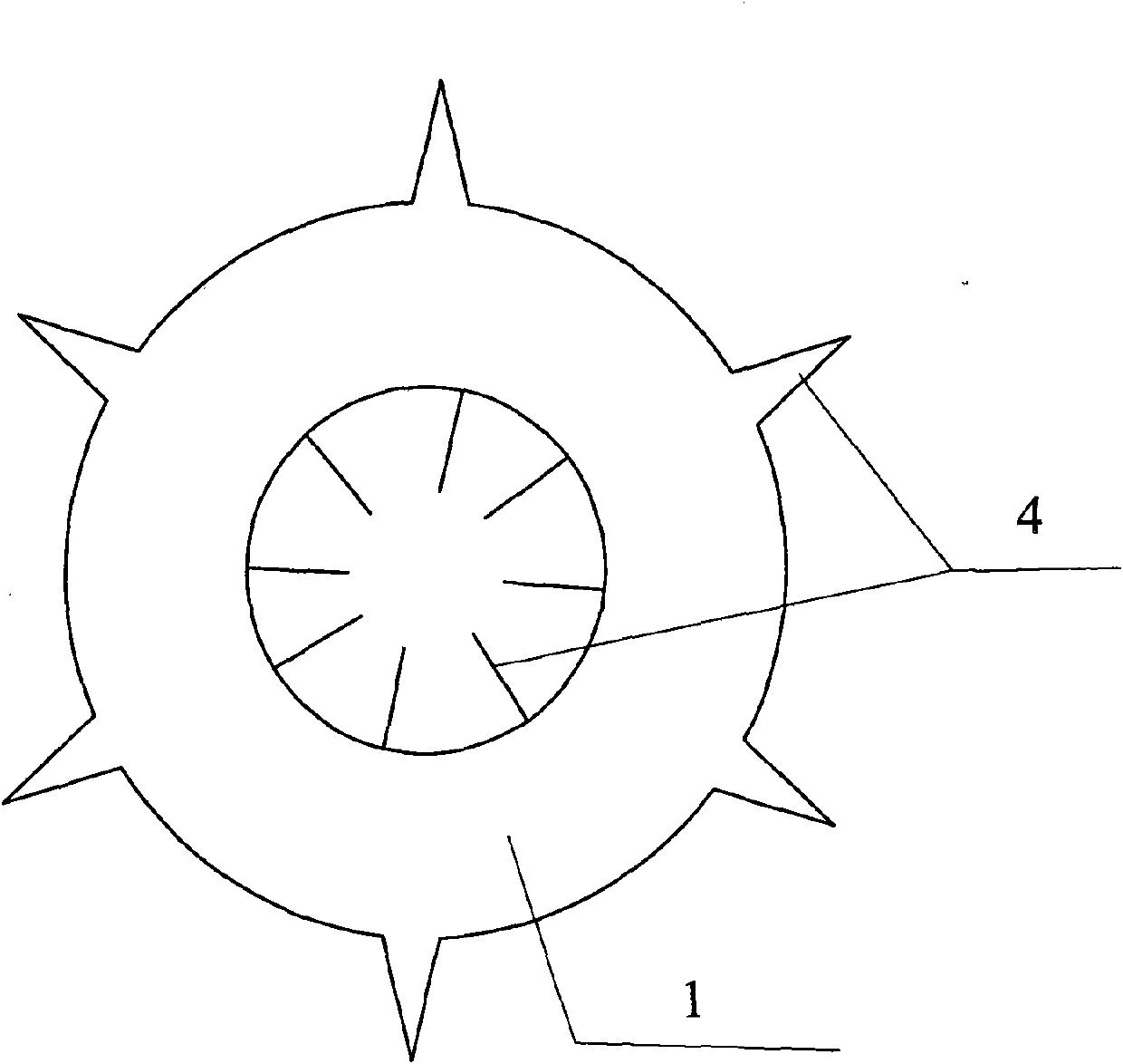
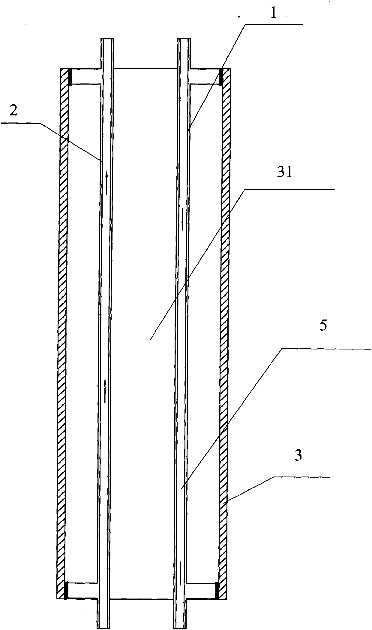
[0043] as attached Figure 1-5 It is a structural schematic diagram of a battery of the present invention.

[0044] After placing the parallel positive heat pipes 1 and negative heat pipes 2 in parallel and at intervals, injection molding is performed on their surfaces to obtain an insulating core 3 with exposed ends of the positive heat pipes 1 and negative heat pipes 2 . The positive heat pipe 1 and the negative heat pipe 2 are filled with insulator 31 at the same time, and the positive heat pipe 1 and the negative heat pipe 2 are located in the insulating core 3, that is, the surface of the positive heat pipe 1 and the negative heat pipe 2 is covered with an insulating layer.

[0045] The quantity of the positive heat pipe 1 and the negative heat pipe 2 is not particularly limited in the present invention, and can be designed according to the size of the positive heat pipe 1 and the negative heat pipe 2 and the size of the electric core 6, etc. The shape of the positive el...

Embodiment 2

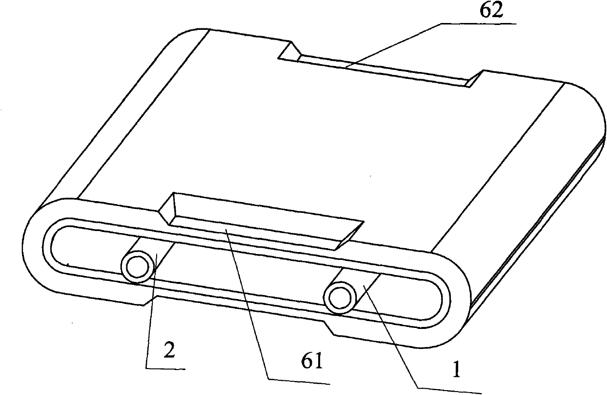
[0054] Such as Figure 6-8 As shown, the battery was prepared in the same manner as in Example 1, except that the positive heat pipe 1 and the negative heat pipe 2 were both made into U-shaped tubes, and the U-shaped bottoms of the U-shaped tubes were placed opposite to each other at intervals. Injection molding to obtain the insulating core member 3 in which the ends of the positive heat conduction pipe 1 and the negative heat conduction pipe 2 are exposed. The positive heat pipe 1 and the negative heat pipe 2 are filled with insulator 31 at the same time, and the positive heat pipe 1 and the negative heat pipe 2 are located in the insulating core 3, that is, the surface of the positive heat pipe 1 and the negative heat pipe 2 is covered with an insulating layer.

[0055]The electric core 6 is wound on the outer surface of the insulating core 3, both ends of the positive heat pipe 1 extend from one end of the electric core 6, and both ends of the negative heat pipe 2 extend f...

Embodiment 3

[0060] Such as Figure 9 As shown, the battery is prepared by the same method as in Example 2, except that a power supply pump and a temperature control system are set between the ends of the two positive electrode heat pipes 1 protruding from one end of the battery in Example 2. The pump, temperature The two ends of the control system and the positive electrode heat pipe 1 are connected through the delivery circulation pipeline 10 of the heat transfer medium 5, and the temperature control system includes a temperature sensing unit capable of inducting the temperature of the heat transfer medium circulating in circulation, such as an induction probe, and a temperature sensing unit capable of controlling the temperature of the heat transfer medium in circulation. The control unit for heating and cooling by the heat-conducting medium. The control unit can include heating fins and radiators and an intelligent control center that controls the work of the heating fins and radiators....


PUM


Abstract

The invention provides a battery, comprising a cover plate, a shell, an electric core and an electrolyte solution. The electric core and the electrolyte are sealed in the battery shell; the cover plate and the shell are in seal connection; and the electric core is provided with a hollow heat pipe, and ends of the heat pipe penetrate through the cover plate and extend out of the battery. The heat pipe arranged in the electric core of the invention has heat conduction function and helps to regulate internal temperature of the electric core. When the internal temperature of the electric core rises rapidly, the electric core can quickly take away the heat in the electric core, so as to cool the battery quickly and improve safety performance of the battery. At the same time, the heat pipe can ensure rapid heat transfer inside the battery and consistent temperature at each place of the electric core, eliminate temperature difference and ensure battery performance. Moreover, the heat pipe in the electric core can play a role of backbone and support to support the electric core, so as to facilitate assembly, as well as benefit winding of the electric core.

Description

technical field [0001] The invention relates to a battery. Background technique [0002] In the context of the depletion of non-renewable resources such as oil and the increasingly serious environmental pollution, people place great expectations on new energy vehicles. The power battery is the heart of the new energy vehicle, and it is required to have excellent power performance, cycle life and environmental tolerance. [0003] The power battery is basically in a mobile state when it is working, and its working environment is diverse. In order to provide high-power discharge and large energy supply, the power battery generally connects a large number of batteries in series and parallel to form a battery pack, and basically stores them in a sealed space for the appearance of the car, and the heat generated during use will continue to accumulate, while the shell dissipates heat The effect is slow and limited, and the internal temperature of the battery cannot be guaranteed ...

Claims


Application Information

Patent Timeline
IPC IPC(8): H01M2/26H01M10/50H01M10/613H01M10/655
CPCY02E60/12Y02T10/7016Y02E60/10
Inventor 刘建国仝志伟
Owner BYD CO LTD
Features
  • Generate Ideas
  • Intellectual Property
  • Life Sciences
  • Materials
  • Tech Scout
  • Unparalleled Data Quality
  • Higher Quality Content
  • 60% Fewer Hallucinations
Learn More