High voltage dynamic reactive compensation device

A compensation device and dynamic technology, applied in reactive power compensation, reactive power adjustment/elimination/compensation, etc., can solve equipment process structure, cost, efficiency problems, volume, cost, power semiconductor devices, efficiency limitations, etc. Problems, Achieve the effects of improving production efficiency, increasing compensation performance, and saving costs

Inactive Publication Date: 2012-10-24
XINFENGGUANG ELECTRONICS TECH CO LTD
View PDF5 Cites 2 Cited by
  • Summary
  • Abstract
  • Description
  • Claims
  • Application Information

AI Technical Summary

Problems solved by technology

However, due to the large difference in power grid conditions, for example, in the case where the grid voltage is above 35KV and large capacity, it is difficult for the general dynamic reactive power compensation device to directly perform high-voltage reactive power compensation. The transformer is installed in front of the dynamic reactive power compensation device. If the capacity required to be compensated is relatively large, or the current required to be compensated is relatively large, the current reactive power compensation device is limited by volume, cost, power semiconductor devices, and efficiency, especially the process structure, cost, and efficiency of the equipment. The problem

Method used


Image

  • High voltage dynamic reactive compensation device
  • High voltage dynamic reactive compensation device
  • High voltage dynamic reactive compensation device

Examples


Embodiment Construction

[0022] The present invention will be further described below in conjunction with the accompanying drawings and embodiments.

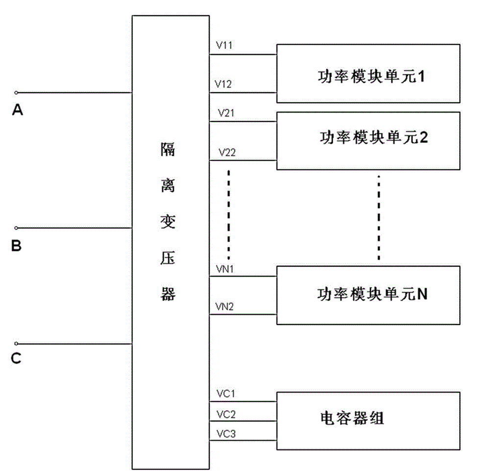
[0023] Such as figure 1 As shown, the system circuit block diagram of the reactive power compensation device of the present invention is given, which includes an isolation transformer, a three-phase capacitor bank, and 3n power module units, where n is a positive integer; Figure 8 It is the circuit diagram of the transformer. The primary side of the transformer shown is a three-phase winding, which is used to connect to the power grid; the secondary side is 3n single-phase windings and a three-phase winding, and the 3n single-phase windings are respectively connected to 3n power modules. The units are connected in phase, and the three-phase winding on the secondary side is used to connect with the three-phase capacitor. The input V11, V12, V21, V22, ... VN1 of the power module unit is connected to the secondary single-phase winding V11, V12, V21, V22,...


PUM


Abstract

The invention discloses a high voltage dynamic reactive compensation device which is characterized by comprising a transformer, a three-phase capacitor group and 3n power module units, wherein 3n single-phase windings and one three-phase winding connected with the three-phase capacitor group are arranged at the secondary side of the transformer; each power module unit is provided with two input ends; control circuits for controlling the communication state between the two input ends are arranged inside the power module units; the output ends of the 3n power module units are respectively connected with 3n single-phase windings; and the control circuits can be rectification H-bridge circuits; and controllable devices are controllable one-way thyristors. By controlling the parallel power module units, the reactive compensation of a high voltage power grid is realized effectively; a mutation current can be buffered by the three-phase capacitors effectively, so that the influence of the power grid is reduced to the minimum. With the adoption of the reactive compensation device, the cost of the whole reactive compensation device is saved, the process mechanism is simplified, and the manufacturing efficiency is improved.

Description

technical field [0001] The invention relates to a high-voltage dynamic reactive power compensation device, more specifically, to a high-voltage dynamic reactive power compensation device in which 3n power module units are connected in parallel on the secondary side of a transformer. Background technique [0002] With the development of modern inverter technology, new technologies have been widely used in industrial equipment. The inverter technology has excellent energy-saving effects, and has the advantages of convenient operation and easy installation and maintenance. However, due to the large difference in power grid conditions, for example, in the case where the grid voltage is above 35KV and large capacity, it is difficult for the general dynamic reactive power compensation device to directly perform high-voltage reactive power compensation. The transformer is installed in front of the dynamic reactive power compensation device. If the capacity required to be compensate...

Claims


Application Information

Patent Timeline
Patent Type & Authority Applications(China)
IPC IPC(8): H02J3/18
CPCY02E40/30
Inventor 李瑞来尹彭飞陈敏
Owner XINFENGGUANG ELECTRONICS TECH CO LTD
Why Eureka
Try Eureka