
Signal detection device and method

A signal detection and signal technology, applied in the field of communications, can solve problems such as data decoding errors, and achieve the effects of controlling power consumption, filtering out out-of-band interference and noise, and effective power consumption

Active Publication Date: 2012-10-24
上海际浩智能科技有限公司
View PDF4 Cites 18 Cited by
  • Summary
  • Abstract
  • Description
  • Claims
  • Application Information

AI Technical Summary

Problems solved by technology

However, affected by the change of received signal strength, the demodulated signal may have false zero-crossing points at other positions. If it is misjudged as the flip point of bi-phase symbol data, it may cause errors in subsequent data decoding.

Method used


Image

  • Signal detection device and method
  • Signal detection device and method
  • Signal detection device and method

Examples


Embodiment Construction

[0034] In the following description, many technical details are proposed in order to enable readers to better understand the application. However, those skilled in the art can understand that without these technical details and various changes and modifications based on the following implementation modes, the technical solution claimed in each claim of the present application can be realized.

[0035] In order to make the purpose, technical solution and advantages of the present invention clearer, the following will further describe the implementation of the present invention in detail in conjunction with the accompanying drawings.

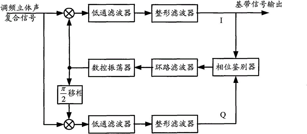
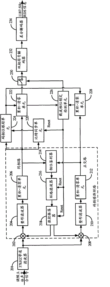
[0036] The core of the present invention is that the signal detection device includes: a Costas loop for coherently demodulating the RDS\RBDS signal; a bit synchronization unit 220 for determining the biphase symbol data inversion point; a code phase tracking unit 224 , for real-time detection of the change of the bit period of the bi-phase symbol...


PUM


Abstract

The invention relates to the field of communication and discloses a signal detection device and method. According to the signal detection device and method disclosed by the invention, as the in-phase branch demodulation output end of a Costas loop not only is coupled with a bit synchronization device but also needs to be coupled with a code phase tracking device, the change condition of the bit cycle of bi-phase mark data is detected in real time by utilizing the code phase tracking device, and when a code phase is deviated, error correction is performed on the code phase in time so as to ensure the decoding correctness of the bi-phase mark data. The problem that a radio data system / radio broadcast data system (RDS / RBDS) signal cannot be correctly decoded because the number of sampling points of the bi-phase mark data in a unit cycle is changed because of the factors such as the stability of a transmitter crystal oscillator, a Doppler effect and the drifting of a receiver crystal oscillator is effectively solved, and therefore, the RDS / RBDS data demodulation is at a correct bit boundary position all along.

Description

technical field [0001] The invention relates to the communication field, in particular to RDS\RBDS signal detection technology. Background technique [0002] The Radio Data System ("RDS" for short) is a communication protocol issued by the European Broadcasting Union ("EBU") for the purpose of adding some digital information to FM radio stations, including station names and program types and program content, etc. Radio Broadcast Data System ("RBDS" for short) is the name of the American version of the RDS system, and there is no essential difference between the two. Therefore, the RDS signal in this application is also the RBDS signal. The RDS system usually uses the DBPSK (Differential Binary Phase Shift Keying) modulation method to transmit digital information on the 57kHz subcarrier. If the FM broadcast transmits a stereo signal (Stereo Signal), there is a pilot signal (Pilot signal) at 19kHz, and the RDS subcarrier signal of 57kHz can be recovered by triple frequency o...

Claims


Application Information

Patent Timeline
IPC IPC(8): H04L27/227H04L27/22
Inventor 黄威庄嘉宜汤江逊龚建
Owner 上海际浩智能科技有限公司
Learn More