Eureka AIR delivers breakthrough ideas for toughest innovation challenges, trusted by R&D personnel around the world.

Method and device for measuring phase nonlinearity of digital phased array receiving channel

A digital phased array and receiving channel technology, applied in radio wave measurement systems, instruments, etc., can solve problems such as high hardware requirements, increased hardware cost burden, low test efficiency, etc., to reduce hardware complexity and cost, and complex algorithms The effect of low precision and fast measurement speed

Pending Publication Date: 2022-05-31
CHINA ELECTRONIC TECH GRP CORP NO 38 RES INST
View PDF2 Cites 2 Cited by
  • Summary
  • Abstract
  • Description
  • Claims
  • Application Information

AI Technical Summary

Problems solved by technology

But this method has the following limitations: First, it is impossible to directly measure the phase nonlinearity of an analog-digital hybrid system like a digital phased array receiving channel (from antenna to ADC baseband data); second, it is difficult to directly measure the phase nonlinearity of a frequency conversion system. Linearity; finally, the test efficiency is low, and the phase nonlinearity of large digital phased arrays with tens of thousands of channels cannot be measured simultaneously
This measurement method has strict requirements on the width of the test pulse, especially when the application of large bandwidth needs to generate extremely narrow pulses, which requires high hardware requirements
At the same time, the effective sampling window of this measurement method is a narrow pulse width. In order to obtain enough data analysis samples, the system sampling interval needs to be much smaller than the narrow pulse width. In broadband applications, ultra-high-speed data acquisition equipment is required, which increases the hardware cost burden.

Method used


Image

  • Method and device for measuring phase nonlinearity of digital phased array receiving channel
  • Method and device for measuring phase nonlinearity of digital phased array receiving channel
  • Method and device for measuring phase nonlinearity of digital phased array receiving channel

Examples


Embodiment Construction

[0071] In order to make the purpose, technical solutions and advantages of the embodiments of the present invention clearer, the technical solutions in the embodiments of the present invention will be clearly and completely described below in conjunction with the embodiments of the present invention. Obviously, the described embodiments are part of the present invention Examples, not all examples. Based on the embodiments of the present invention, all other embodiments obtained by persons of ordinary skill in the art without creative efforts fall within the protection scope of the present invention.

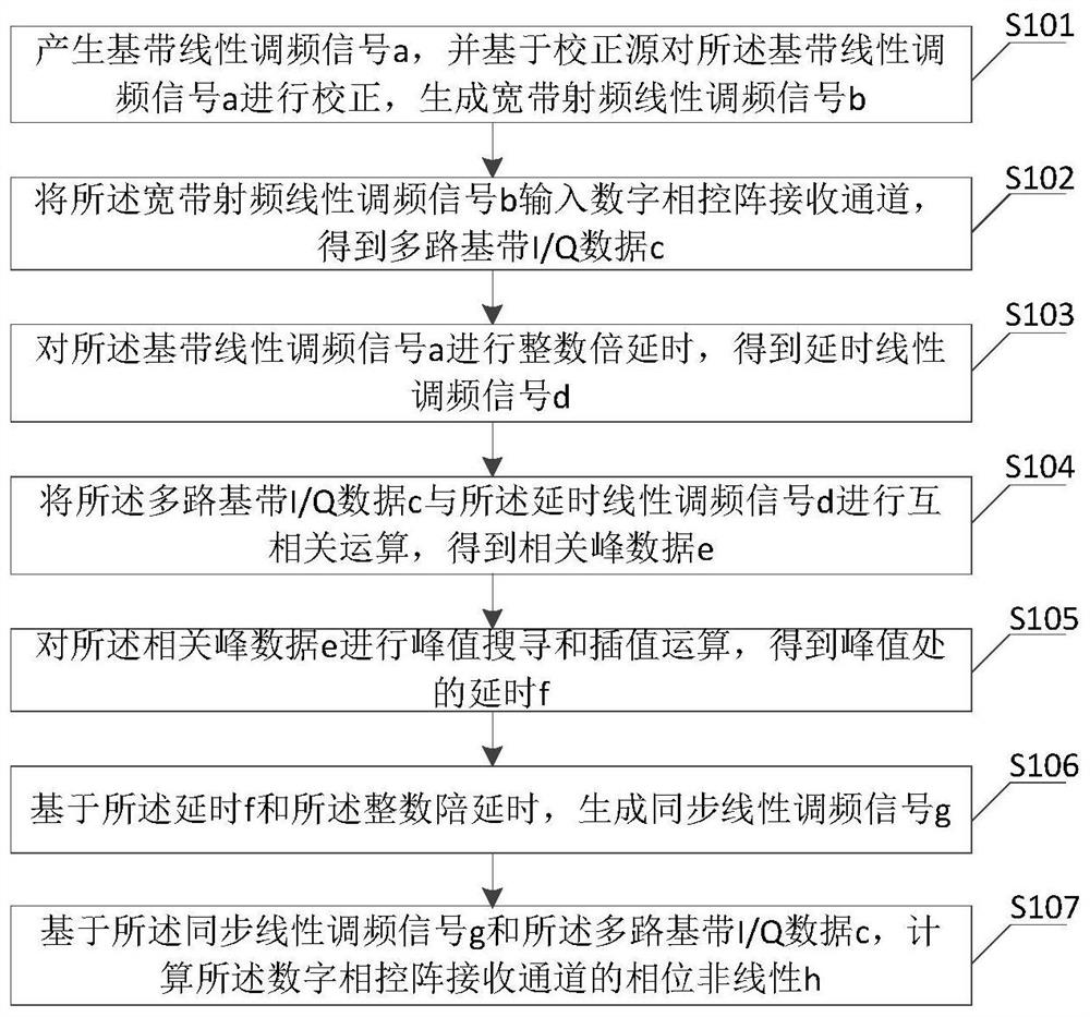
[0072] refer to figure 1 , figure 1 It is a schematic flow chart of an embodiment of a method for measuring the phase nonlinearity of a digital phased array receiving channel of the present invention, and the method includes the following steps:

[0073] S101. Generate a baseband chirp signal a, and correct the baseband chirp signal a based on a correction source to generate a ...


PUM


Abstract

The invention discloses a method and a device for measuring the phase nonlinearity of a digital phased array receiving channel, and belongs to the technical field of input signal testing. The method comprises the following steps: generating a baseband linear frequency modulation signal a, performing correction based on a correction signal a, and generating a broadband radio frequency linear frequency modulation signal b and a delay linear frequency modulation signal d; inputting the wide signal b into a digital phased array receiving channel to obtain multi-path baseband I / Q data c; performing cross-correlation operation on the multi-path baseband I / Q data c and the signal d to obtain correlation peak data e; carrying out peak value searching and interpolation operation on the correlation peak data e to obtain delay f at a peak value; generating a synchronous linear frequency modulation signal g based on the delay f and the integer accompanying delay; and calculating the phase nonlinearity h of the digital phased array receiving channel based on the signal g and the multi-path baseband I / Q data c. The method is small in algorithm software resource overhead and high in measurement speed, and auxiliary narrow pulse generation equipment and ultra-high-speed data acquisition equipment are not needed.

Description

technical field [0001] The invention relates to the technical field of signal testing, in particular to a method and device for measuring the phase nonlinearity of a receiving channel of a digital phased array. Background technique [0002] Phase nonlinearity is one of the important performance indicators of digital phased array receiving channel. An ideal transmission system has no phase nonlinear distortion. However, due to the influence of factors such as filters, mixers, amplifiers, and impedance matching networks in the receiving chain, the phase and frequency in the frequency band do not have a strict linear relationship. In broadband systems The performance is particularly obvious. The phase nonlinear index directly determines the degree of distortion of the signal passing through the transmission system, which not only affects the pulse pressure sidelobe performance of the radar system or the intersymbol interference performance of the communication system, but also...

Claims


Application Information

Patent Timeline
Patent Type & Authority Applications(China)
IPC IPC(8): G01S7/40
CPCG01S7/40G01S7/4021
Inventor 吴兵陈阳张晓光王笃文杜丽军常灿灿管淑洁赵林超
Owner CHINA ELECTRONIC TECH GRP CORP NO 38 RES INST
Why Eureka
Eureka Blog
Learn More