
Remote diagnosis method of television fault, television and system

A technology of fault remote diagnosis and TV, which is applied in the field of TV, can solve the problems of high maintenance cost and manual maintenance, and achieve the effect of reducing maintenance cost and improving maintenance efficiency

Active Publication Date: 2012-10-24
SHENZHEN SKYWORTH RGB ELECTRONICS CO LTD
View PDF9 Cites 38 Cited by
  • Summary
  • Abstract
  • Description
  • Claims
  • Application Information

AI Technical Summary

Problems solved by technology

[0003] The main purpose of the present invention is to provide a method for remote diagnosis of TV faults, aiming to solve the technical problem of high maintenance cost caused by manual maintenance in the prior art

Method used

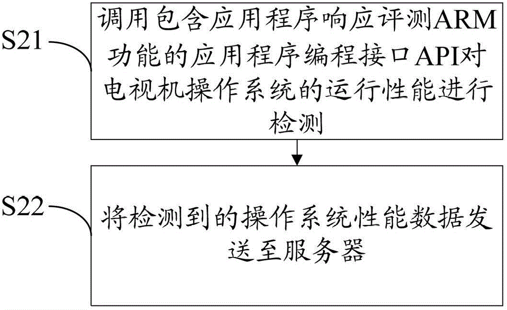

Image

  • Remote diagnosis method of television fault, television and system
  • Remote diagnosis method of television fault, television and system
  • Remote diagnosis method of television fault, television and system

Examples


Embodiment Construction

[0033] It should be understood that the specific embodiments described here are only used to explain the present invention, not to limit the present invention.

[0034] The core idea of ​​the present invention is to provide a method that can solve the problem of software failure through remote service through the network. At the same time, the user can regularly check the operation status of the TV, and then upload the inspection data to the server, and the remote service engineer can use the uploaded data. To judge the usage status of the TV, and put forward some suggestions for optimizing the operation of the TV system.

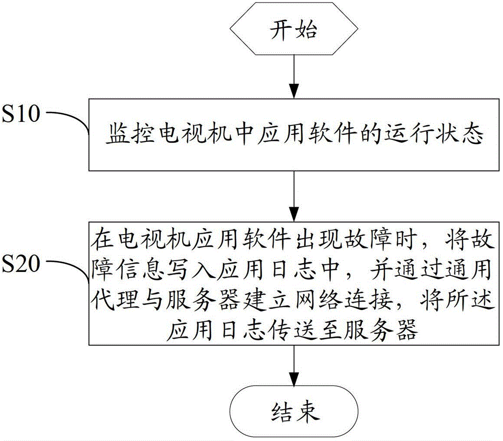
[0035] refer to figure 1 , figure 1 It is a flow chart of an embodiment of the method for remote diagnosis of TV faults according to the present invention. Such as figure 1 As shown, the process includes the following steps:

[0036] Step S10, monitor the running state of the application software in the TV; in the embodiment of the present invention, th...


PUM


Abstract

The invention discloses a remote diagnosis method of a television fault. The method includes monitoring running state of application software in a television, writing fault information into an application log when the application software of the television has the fault, building network connection through general agency and a server and transmitting the application log to the server. The television and a remote fault diagnosis system of the television are further disclosed. The method, the television and the system can reduce maintenance cost of the television.

Description

technical field [0001] The invention belongs to the technical field of televisions, and in particular relates to a method for remote diagnosis of television faults, a television and a system. Background technique [0002] With the development of IC technology, the internal structure of TV sets is becoming more and more integrated. Due to the highly integrated and modularized hardware, the probability of hardware failures in TV sets is getting lower and lower. However, as the TV software system becomes more and more complex and more and more applications are installed, the probability of software problems such as data corruption on the TV increases greatly. At this stage, if there is a software problem in the TV set, after-sales engineers need to come to the door to solve the problem. This will not only lengthen the maintenance cycle, but also increase the labor cost of the enterprise. Contents of the invention [0003] The main purpose of the present invention is to prov...

Claims


Application Information

Patent Timeline
IPC IPC(8): H04N17/00H04N21/4425
Inventor 赵新科李俊涛许锟
Owner SHENZHEN SKYWORTH RGB ELECTRONICS CO LTD
Learn More